# Creating DHCP Server/VLAN on vSZ APs

<details id="bkmrk-introduction-dhcp%2Fna"><summary>Introduction</summary>

DHCP/NAT functionality on SZ-managed APs and DPs (data planes) allows customers to reduce costs and complexity by removing the need for DHCP server/NAT router to provide IP addresses to clients.

Three general DHCP scenarios are supported:

- SMB Single AP: DHCP is running on a single AP only. This AP also functions as the Gateway AP.
- SMB Multiple APs (&lt;12): DHCP service is running on all APs, among which two of the APs will be Gateway APs. These two Gateway APs will provide the IP addresses as well as Internet connectivity to the clients via NAT.
- Enterprise (&gt;12): For Enterprise sites, an additional on-site vSZ-D will be deployed at the remote site which will assume the responsibilities of performing DHCP/NAT functions. Therefore, DHCP/NAT service will not be running on any APs (they will serve clients only), while the DHCP/NAT services are provided by the onsite vSZ-D.

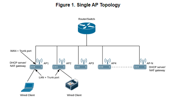
<div class="table-wrap"><table class="relative-table confluenceTable"><colgroup><col></col><col></col></colgroup><tbody><tr><td class="confluenceTd">## Single AP Topology

All the APs in the zone get their IP from the WAN router and provides the DHCP/NAT service. If H510/H320 is configured as GAP by the manual port selection, then LAN1 and LAN2 configuration will be pushed to eth1 and eth2 ports of H510/H320 APs instead of eth0 and eth1 ports.

Each AP in this zone is running it’s own DHCP server instance.  
Typically configured when APs are at different sites and roaming is not required.

</td><td class="confluenceTd">[![image.png](https://techblog.jcditservices.com/uploads/images/gallery/2024-08/scaled-1680-/6PPimage.png)](https://techblog.jcditservices.com/uploads/images/gallery/2024-08/6PPimage.png)

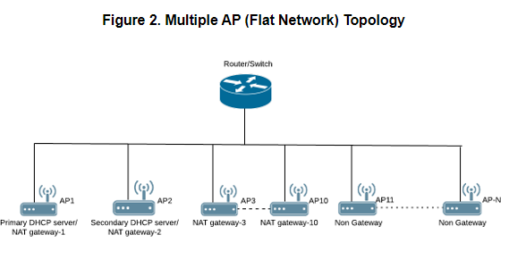
</td></tr><tr><td class="confluenceTd">## Multiple AP (Flat Network) Topology

All the APs in the zone get their IP from the WAN router and designated APs to provide the DHCP/NAT service. A maximum of two APs be can select for DHCP service (Primary and Secondary) and ten APs for NAT Gateway.

Designated APs in this zone are running the DHCP Server instance.  
Typically configured when multiple APs are at the same site and roaming across APs is needed.

</td><td class="confluenceTd">[![image.png](https://techblog.jcditservices.com/uploads/images/gallery/2024-08/scaled-1680-/HIximage.png)](https://techblog.jcditservices.com/uploads/images/gallery/2024-08/HIximage.png)

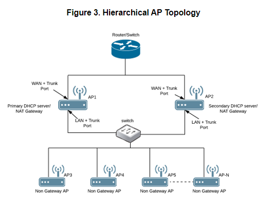
</td></tr><tr><td class="confluenceTd">## Hierarchical AP Topology

Designated APs provide the DHCP/NAT service. Gateway APs (GAPs) get the IP address from the WAN router and non-gateway APs get the IP from the Gateway APs. If H510/H320 is configured as GAP by the manual port selection, then LAN1 and LAN2 configuration will be pushed to eth1 and eth2 ports of H510/H320 APs instead of eth0 and eth1 ports. In order to configure eth0 ports of H510/H320, the user needs to configure LAN5/LAN3 Ports respectively for the H510/H320 APs.

Designated APs in this zone are running the DHCP Server instance.  
The DHCP server APs connected to the WAN, the rest of APs get their Private IP address from a local IP Pool with VLAN ID 1 from the DHCP Server AP.

</td><td class="confluenceTd">[![image.png](https://techblog.jcditservices.com/uploads/images/gallery/2024-08/scaled-1680-/05Pimage.png)](https://techblog.jcditservices.com/uploads/images/gallery/2024-08/05Pimage.png)

</td></tr></tbody></table>

</div></details><details id="bkmrk-method-login-to-the-"><summary>Method</summary>

Login to the vSZ and Navigate to **Services and Profiles** then **DHCP &amp; NAT**. Locate the domain under the organisation pane, then expand the required domain and highlight the zone you wish to configure your DHCP service. There will be an option to **Enable DHCP Service**. Enable this, to be directed through a configuration wizard.

[![image.png](https://techblog.jcditservices.com/uploads/images/gallery/2024-08/scaled-1680-/uO8image.png)](https://techblog.jcditservices.com/uploads/images/gallery/2024-08/uO8image.png)

Select the appropriate **Base Settings**. The options are **Single AP** (1), **Multiple APs** (&lt;12), or **Hierarchal APs** (&gt;12). For the purpose of this KB we will only be looking at **Single** **AP** or **Multiple AP** scenarios as Hierarchal will require a data plane. Click **Next** to continue.

[![image.png](https://techblog.jcditservices.com/uploads/images/gallery/2024-08/scaled-1680-/iPpimage.png)](https://techblog.jcditservices.com/uploads/images/gallery/2024-08/iPpimage.png)

Create a **DHCP Pool** by clicking on the **+**. A new page will pop up. Simply enter the required information and click **OK**. Repeat more networks if necessary. Once done, highlight and move the Pools from **Available Pools** to **Selected Pools** and click **Next** to continue.

[![image.png](https://techblog.jcditservices.com/uploads/images/gallery/2024-08/scaled-1680-/z9fimage.png)](https://techblog.jcditservices.com/uploads/images/gallery/2024-08/z9fimage.png)

[![image.png](https://techblog.jcditservices.com/uploads/images/gallery/2024-08/scaled-1680-/Cc9image.png)](https://techblog.jcditservices.com/uploads/images/gallery/2024-08/Cc9image.png)

[![image.png](https://techblog.jcditservices.com/uploads/images/gallery/2024-08/scaled-1680-/35Ximage.png)](https://techblog.jcditservices.com/uploads/images/gallery/2024-08/35Ximage.png)

On the next page, select your **Gateway AP(s).** The options are either **Automatic** or **Manual**. If you are selecting **Manual**, you will need to move AP(s) similar to moving the Pool(s) in the previous step and select a Primary and Secondary AP. Click **Next** to continue.

[![image.png](https://techblog.jcditservices.com/uploads/images/gallery/2024-08/scaled-1680-/Jpoimage.png)](https://techblog.jcditservices.com/uploads/images/gallery/2024-08/Jpoimage.png)

[![image.png](https://techblog.jcditservices.com/uploads/images/gallery/2024-08/scaled-1680-/RyJimage.png)](https://techblog.jcditservices.com/uploads/images/gallery/2024-08/RyJimage.png)

Review your configuration and click **OK** to confirm.

[![image.png](https://techblog.jcditservices.com/uploads/images/gallery/2024-08/scaled-1680-/T5kimage.png)](https://techblog.jcditservices.com/uploads/images/gallery/2024-08/T5kimage.png)

Configure your WLANs now as you normally would, however, ensure that under **Advanced Options** that your **Access VLAN** is set as per your DHCP profile.

[![image.png](https://techblog.jcditservices.com/uploads/images/gallery/2024-08/scaled-1680-/hmPimage.png)](https://techblog.jcditservices.com/uploads/images/gallery/2024-08/hmPimage.png)

Perform testing to ensure all is working as expected.

To prevent the two network users from being able to communicate with one another you must now create **L3 Access** **Control** profile(s). This will look something like the following:

*Action: Block*

*Source Network Address/Subnet Mask*

*Destination Network Address/Subnet Mask*

So for example, if we want to block communication between our Private and Guest wireless networks we will need to create two rules and affix these to the respective WLAN.

<u>*Block Guest on Private*</u>

*Action: Block*

*Source 192.168.66.0/24*

*Destination 192.168.99.0/24*

<u>*Block Private on Guest*</u>

*Action: Block*

*Source 192.168.99.0/24*

*Destination 192.168.66.0/24*

Navigate to **Firewall** then **L3 Access Control**, highlight the appropriate domain then click **Create**. A new page will pop up. Provide a **Name** and **Description** and create a rule by clicking **Create**. Add a **Description**, under **Access** select **Block** from the drop-down. Enter the **Source** and **Destination Network Address** and **Subnet Mask**. Set the **Direction** to **Dual**. Create profiles for any necessary networks.

[![image.png](https://techblog.jcditservices.com/uploads/images/gallery/2024-08/scaled-1680-/fbQimage.png)](https://techblog.jcditservices.com/uploads/images/gallery/2024-08/fbQimage.png)

[![image.png](https://techblog.jcditservices.com/uploads/images/gallery/2024-08/scaled-1680-/bHeimage.png)](https://techblog.jcditservices.com/uploads/images/gallery/2024-08/bHeimage.png)

Apply these to your WLANs by navigating to **Wireless LANs**, highlight and configure your WLAN, scroll down to **Firewall** and select the tickbox for **Enable WLAN specific**. Under the **L3 Access Control Policy** use the dropdown to select the appropriate profile. Repeat for all necessary WLANs.

[![image.png](https://techblog.jcditservices.com/uploads/images/gallery/2024-08/scaled-1680-/KwXimage.png)](https://techblog.jcditservices.com/uploads/images/gallery/2024-08/KwXimage.png)

Perform testing to ensure all is working as expected.

Notes

<div class="confluence-information-macro-body">- There is a limitation of 1000 IPs per DHCP Pool
- When running SMB **Multiple AP** mode, 10 IPs will be reserved for Gateway APs
- You can navigate to **Services and Profiles** then **DHCP &amp; NAT** to obtain information on the DHCP server stats

</div></details>