# Ruckus

# Access Points

Ruckus Access Points

# Ruckus Access Point LED Status

<details id="bkmrk-introduction-this-se"><summary>Introduction</summary>

This section describes the physical LED status and descriptions of the Ruckus Access Points.

</details><details id="bkmrk-led-behaviour-pwr-of"><summary>LED Behaviour</summary>

If you believe an AP is not operating normally, checking the onboard LEDs can help you determine the AP behavior.

If wireless devices that are connected to your APs are experiencing connectivity issues, check the AP LEDs to determine if your APs are operating normally.

<div class="note note note_note" id="bkmrk-note%3A%C2%A0in-the-followi">**<span class="note__title">Note:</span>** In the following diagram, some newer APs display CTL instead of DIR for the LED, second LED from the left.</div><figure class="fig fignone" id="bkmrk-checking-the-ap-leds"><figcaption><span class="fig-title">**Checking the AP LEDs to Determine if the AP is Operating Properly**  
</span>[![image.png](https://techblog.jcditservices.com/uploads/images/gallery/2024-08/scaled-1680-/cwZimage.png)](https://techblog.jcditservices.com/uploads/images/gallery/2024-08/cwZimage.png)

The following table describes the LEDs on the AP, how they behave, and what they mean.

<table class="table" id="bkmrk-ap-leds-and-what-the"><caption><span class="title" id="bkmrk-ap-leds-and-what-the-1">AP LEDs and What They Mean</span></caption><colgroup><col></col><col></col><col></col></colgroup><thead class="thead"><tr class="row"><th class="entry rowsep-1" id="bkmrk-led">LED</th><th class="entry rowsep-1" id="bkmrk-color">Color</th><th class="entry rowsep-1" id="bkmrk-description">Description</th></tr></thead><tbody class="tbody"><tr class="row"><td class="entry rowsep-1" headers="GUID-84886D1C-F63B-44D0-8731-92E3CE6E1951__TABLE_TK5_B3T_DV__entry__1 " rowspan="2">PWR</td><td class="entry rowsep-1" headers="GUID-84886D1C-F63B-44D0-8731-92E3CE6E1951__TABLE_TK5_B3T_DV__entry__2 ">Solid green</td><td class="entry rowsep-1" headers="GUID-84886D1C-F63B-44D0-8731-92E3CE6E1951__TABLE_TK5_B3T_DV__entry__3 ">The AP has received a local IP address from the DHCP server.</td></tr><tr class="row"><td class="entry rowsep-1" headers="GUID-84886D1C-F63B-44D0-8731-92E3CE6E1951__TABLE_TK5_B3T_DV__entry__2 ">Slow flashing green</td><td class="entry rowsep-1" headers="GUID-84886D1C-F63B-44D0-8731-92E3CE6E1951__TABLE_TK5_B3T_DV__entry__3 ">A local network, DHCP, or VLAN issue has been detected.</td></tr><tr class="row"><td class="entry rowsep-1" headers="GUID-84886D1C-F63B-44D0-8731-92E3CE6E1951__TABLE_TK5_B3T_DV__entry__1 " rowspan="3">DIR or CTL</td><td class="entry rowsep-1" headers="GUID-84886D1C-F63B-44D0-8731-92E3CE6E1951__TABLE_TK5_B3T_DV__entry__2 ">Solid green</td><td class="entry rowsep-1" headers="GUID-84886D1C-F63B-44D0-8731-92E3CE6E1951__TABLE_TK5_B3T_DV__entry__3 ">The AP is connected to the cloud controller.</td></tr><tr class="row"><td class="entry rowsep-1" headers="GUID-84886D1C-F63B-44D0-8731-92E3CE6E1951__TABLE_TK5_B3T_DV__entry__2 ">Fast flashing green</td><td class="entry rowsep-1" headers="GUID-84886D1C-F63B-44D0-8731-92E3CE6E1951__TABLE_TK5_B3T_DV__entry__3 ">The AP is obtaining updates from the cloud controller.</td></tr><tr class="row"><td class="entry rowsep-1" headers="GUID-84886D1C-F63B-44D0-8731-92E3CE6E1951__TABLE_TK5_B3T_DV__entry__2 ">Slow flashing green</td><td class="entry rowsep-1" headers="GUID-84886D1C-F63B-44D0-8731-92E3CE6E1951__TABLE_TK5_B3T_DV__entry__3 ">The AP is disconnected from the Internet. Check your network firewall settings.</td></tr><tr class="row"><td class="entry rowsep-1" headers="GUID-84886D1C-F63B-44D0-8731-92E3CE6E1951__TABLE_TK5_B3T_DV__entry__1 " rowspan="3">2.4G and 5GHz</td><td class="entry rowsep-1" headers="GUID-84886D1C-F63B-44D0-8731-92E3CE6E1951__TABLE_TK5_B3T_DV__entry__2 ">Solid green</td><td class="entry rowsep-1" headers="GUID-84886D1C-F63B-44D0-8731-92E3CE6E1951__TABLE_TK5_B3T_DV__entry__3 ">The network is up and at least one wireless client is associated with it.</td></tr><tr class="row"><td class="entry rowsep-1" headers="GUID-84886D1C-F63B-44D0-8731-92E3CE6E1951__TABLE_TK5_B3T_DV__entry__2 ">Solid orange</td><td class="entry rowsep-1" headers="GUID-84886D1C-F63B-44D0-8731-92E3CE6E1951__TABLE_TK5_B3T_DV__entry__3 ">The network is up, but no clients are associated with it.</td></tr><tr class="row"><td class="entry rowsep-1" headers="GUID-84886D1C-F63B-44D0-8731-92E3CE6E1951__TABLE_TK5_B3T_DV__entry__2 ">Off</td><td class="entry rowsep-1" headers="GUID-84886D1C-F63B-44D0-8731-92E3CE6E1951__TABLE_TK5_B3T_DV__entry__3 ">The network is down.</td></tr><tr class="row"><td class="entry rowsep-1" headers="GUID-84886D1C-F63B-44D0-8731-92E3CE6E1951__TABLE_TK5_B3T_DV__entry__1 ">AIR</td><td class="entry rowsep-1" headers="GUID-84886D1C-F63B-44D0-8731-92E3CE6E1951__TABLE_TK5_B3T_DV__entry__2 ">Always off</td><td class="entry rowsep-1" headers="GUID-84886D1C-F63B-44D0-8731-92E3CE6E1951__TABLE_TK5_B3T_DV__entry__3 ">Not used</td></tr></tbody></table>

</figcaption></figure></details>

# Upgrade Ruckus AP via SSH/FTP

<details id="bkmrk-introduction-should-"><summary>Introduction</summary>

Should you have an issue upgrading a Ruckus AP's firmware via Web GUI, you can upgrade alternatively by using a combination of an SSH session and an FTP Server.

Putty - SSH Software: [https://www.chiark.greenend.org.uk/~sgtatham/putty/latest.html](https://www.chiark.greenend.org.uk/~sgtatham/putty/latest.html)

MobaXterm - FTP Software: [https://mobaxterm.mobatek.net/download-home-edition.html](https://mobaxterm.mobatek.net/download-home-edition.html)

</details><details id="bkmrk-method-%28stage-1%29-sta"><summary>Method (Stage 1)</summary>

Start your FTP server. For the purpose of this document, we will be using MobaXterms FTP server.

[![image.png](https://techblog.jcditservices.com/uploads/images/gallery/2024-08/scaled-1680-/Xdbimage.png)](https://techblog.jcditservices.com/uploads/images/gallery/2024-08/Xdbimage.png)

Edit the FTP server by clicking the TOOLS icon.

[![image.png](https://techblog.jcditservices.com/uploads/images/gallery/2024-08/scaled-1680-/tK6image.png)](https://techblog.jcditservices.com/uploads/images/gallery/2024-08/tK6image.png)

Select the location of the file (the desktop in this case), username, and password, and leave the port number as default (21). Click 'OK' to confirm the settings.

[![image.png](https://techblog.jcditservices.com/uploads/images/gallery/2024-08/scaled-1680-/WiUimage.png)](https://techblog.jcditservices.com/uploads/images/gallery/2024-08/WiUimage.png)

Open the server again and click the PLAY/START button to start the server.

[![image.png](https://techblog.jcditservices.com/uploads/images/gallery/2024-08/scaled-1680-/nEaimage.png)](https://techblog.jcditservices.com/uploads/images/gallery/2024-08/nEaimage.png)

</details><details id="bkmrk-method-%28stage-2%29-ssh"><summary>Method (Stage 2)</summary>

SSH into the AP using Putty. Use the IP address of the Access Point in the 'Hostname (or IP address)' section. Ensure that you are using port 22 and that SSH is selected. Click 'Open' to begin the connection.

[![image.png](https://techblog.jcditservices.com/uploads/images/gallery/2024-08/scaled-1680-/rlHimage.png)](https://techblog.jcditservices.com/uploads/images/gallery/2024-08/rlHimage.png)

Log in with the Access Points username and password.

[![image.png](https://techblog.jcditservices.com/uploads/images/gallery/2024-08/scaled-1680-/fCdimage.png)](https://techblog.jcditservices.com/uploads/images/gallery/2024-08/fCdimage.png)

This will either be default or defined by the administrator. Once logged in use the following command to begin the upgrade process:

fw set control **FILENAME INCLUDING EXTENSION**

fw set proto **TRANSFER PROTOCOL METHOD**

fw set port **PORT NUMBER**

fw set host **IP ADDRESS/HOSTNAME OF FTP SERVER**

fw set user **SERVER USERNAME**

fw set password **SERVER PASSWORD**

fw up

For example;

fw set control **R510\_104.0.0.0.1347.bl7**

fw set proto **ftp**

fw set port **21**

fw set host **192.168.88.254**

fw set user **username1**

fw set password **password1**

fw up

[![image.png](https://techblog.jcditservices.com/uploads/images/gallery/2024-08/scaled-1680-/tenimage.png)](https://techblog.jcditservices.com/uploads/images/gallery/2024-08/tenimage.png)

Once successful you will receive a 'Completed' status. You **must** now reboot the AP by typing 'reboot' no quotes and pressing enter to confirm.

Once booted, confirm your work by typing 'get version' no quotes to ensure that the file is successfully uploaded/updated.

</details>

# Ruckus T750SE

The RUCKUS T750SE is a high-end dual-band outdoor Wi-Fi 6 AP with external antenna connectors that supports 8 spatial streams (4x4:4 in 5GHz, 4x4:4 in 2.4GHz).

The T750SE provides advanced 802.11ax features including OFDMA and MU-MIMO, and supports up to 1,024 client connections with increased capacity, improved coverage and performance in ultra-high density environments.

The T750SE includes a 2.5 GbE Ethernet PoE+ port for high speed Ethernet backhaul, along with an SFP fiber port for fiber backhaul. Additionally, it includes built-in GPS, USB port, gigabit PoE out port, and IP-67 rated weather proofing.

This section describes the physical features of the <span class="ph" id="bkmrk-ruckus-unleashed">RUCKUS Unleashed</span> T750SE AP.

<span class="fig--title-label">Figure 1. </span>Unleashed T750SE Access Point

[![image.png](https://techblog.jcditservices.com/uploads/images/gallery/2024-08/scaled-1680-/JPEimage.png)](https://techblog.jcditservices.com/uploads/images/gallery/2024-08/JPEimage.png)

1. SFP port
2. PoE IN
3. PoE OUT
4. AC port

##### Front Panel

The T750SE AP features five LEDs on its front panel.

<table class="table frame-all align-left" id="bkmrk-table-1.%C2%A0front-panel"><caption>**<span class="table--title-label">Table 1. </span><span class="title" id="bkmrk-front-panel-leds">Front Panel LEDs</span>**</caption><colgroup><col></col><col></col><col></col></colgroup><thead class="thead"><tr class="row"><th class="entry" id="bkmrk-led">LED</th><th class="entry" id="bkmrk-status">Status</th><th class="entry" id="bkmrk-description">Description</th></tr></thead><tbody class="tbody"><tr class="row"><td class="entry" headers="GUID-21C20FCE-A1E5-4FC3-9D69-8E334CE24D05__TABLE_P2Q_BGT_FT__entry__1 ">PWR</td><td class="entry align-center" headers="GUID-21C20FCE-A1E5-4FC3-9D69-8E334CE24D05__TABLE_P2Q_BGT_FT__entry__2 ">![](https://docs-be.commscope.com/bundle/unleashed-200.14-onlinehelp/page/GUID-619C8395-26AF-47EE-B2F6-719FE0FD32F7-low.png?_LANG=enus)Off</td><td class="entry" headers="GUID-21C20FCE-A1E5-4FC3-9D69-8E334CE24D05__TABLE_P2Q_BGT_FT__entry__3 ">No power connected.</td></tr><tr class="row"><td class="entry" headers="GUID-21C20FCE-A1E5-4FC3-9D69-8E334CE24D05__TABLE_P2Q_BGT_FT__entry__1 ">PWR</td><td class="entry align-center" headers="GUID-21C20FCE-A1E5-4FC3-9D69-8E334CE24D05__TABLE_P2Q_BGT_FT__entry__2 ">![](https://docs-be.commscope.com/bundle/unleashed-200.14-onlinehelp/page/GUID-E2B8F33B-1A0E-42BF-BA6A-C062F7C8D273-low.png?_LANG=enus)Solid Red</td><td class="entry" headers="GUID-21C20FCE-A1E5-4FC3-9D69-8E334CE24D05__TABLE_P2Q_BGT_FT__entry__3 ">Boot up in process.</td></tr><tr class="row"><td class="entry" headers="GUID-21C20FCE-A1E5-4FC3-9D69-8E334CE24D05__TABLE_P2Q_BGT_FT__entry__1 ">PWR</td><td class="entry align-center" headers="GUID-21C20FCE-A1E5-4FC3-9D69-8E334CE24D05__TABLE_P2Q_BGT_FT__entry__2 ">![](https://docs-be.commscope.com/bundle/unleashed-200.14-onlinehelp/page/GUID-E382A8F9-74D2-42E6-8E1B-58BA3F413E3E-low.gif?_LANG=enus)Flashing Green</td><td class="entry" headers="GUID-21C20FCE-A1E5-4FC3-9D69-8E334CE24D05__TABLE_P2Q_BGT_FT__entry__3 ">System started, no routable IP address detected.</td></tr><tr class="row"><td class="entry" headers="GUID-21C20FCE-A1E5-4FC3-9D69-8E334CE24D05__TABLE_P2Q_BGT_FT__entry__1 ">PWR</td><td class="entry align-center" headers="GUID-21C20FCE-A1E5-4FC3-9D69-8E334CE24D05__TABLE_P2Q_BGT_FT__entry__2 ">![](https://docs-be.commscope.com/bundle/unleashed-200.14-onlinehelp/page/GUID-2F7C38C0-5586-4CE9-BD42-1F69282E59FE-low.png?_LANG=enus)Solid Green</td><td class="entry" headers="GUID-21C20FCE-A1E5-4FC3-9D69-8E334CE24D05__TABLE_P2Q_BGT_FT__entry__3 ">Routable IP address received.</td></tr><tr class="row"><td class="entry" headers="GUID-21C20FCE-A1E5-4FC3-9D69-8E334CE24D05__TABLE_P2Q_BGT_FT__entry__1 ">CTL</td><td class="entry align-center" headers="GUID-21C20FCE-A1E5-4FC3-9D69-8E334CE24D05__TABLE_P2Q_BGT_FT__entry__2 ">![](https://docs-be.commscope.com/bundle/unleashed-200.14-onlinehelp/page/GUID-2101B6F0-C499-4474-9797-2ACB1628D0B3-low.png?_LANG=enus)Off</td><td class="entry" headers="GUID-21C20FCE-A1E5-4FC3-9D69-8E334CE24D05__TABLE_P2Q_BGT_FT__entry__3 ">Unleashed Member AP.</td></tr><tr class="row"><td class="entry" headers="GUID-21C20FCE-A1E5-4FC3-9D69-8E334CE24D05__TABLE_P2Q_BGT_FT__entry__1 ">CTL</td><td class="entry align-center" headers="GUID-21C20FCE-A1E5-4FC3-9D69-8E334CE24D05__TABLE_P2Q_BGT_FT__entry__2 ">![](https://docs-be.commscope.com/bundle/unleashed-200.14-onlinehelp/page/GUID-B27377AB-E9CA-46B8-BCB6-DE5FF69D69FB-low.gif?_LANG=enus)Flashing Green (slow, every 2 seconds)</td><td class="entry" headers="GUID-21C20FCE-A1E5-4FC3-9D69-8E334CE24D05__TABLE_P2Q_BGT_FT__entry__3 ">Network problem. Cannot contact Unleashed Master.</td></tr><tr class="row"><td class="entry" headers="GUID-21C20FCE-A1E5-4FC3-9D69-8E334CE24D05__TABLE_P2Q_BGT_FT__entry__1 ">CTL</td><td class="entry align-center" headers="GUID-21C20FCE-A1E5-4FC3-9D69-8E334CE24D05__TABLE_P2Q_BGT_FT__entry__2 ">![](https://docs-be.commscope.com/bundle/unleashed-200.14-onlinehelp/page/GUID-FE7E22DA-D208-4A93-839D-6D3A17034599-low.gif?_LANG=enus)Flashing Green (fast, 2x per second)</td><td class="entry" headers="GUID-21C20FCE-A1E5-4FC3-9D69-8E334CE24D05__TABLE_P2Q_BGT_FT__entry__3 ">Receiving configuration or image upgrade.</td></tr><tr class="row"><td class="entry" headers="GUID-21C20FCE-A1E5-4FC3-9D69-8E334CE24D05__TABLE_P2Q_BGT_FT__entry__1 ">CTL</td><td class="entry align-center" headers="GUID-21C20FCE-A1E5-4FC3-9D69-8E334CE24D05__TABLE_P2Q_BGT_FT__entry__2 ">![](https://docs-be.commscope.com/bundle/unleashed-200.14-onlinehelp/page/GUID-B8BE0204-9D01-4053-BE89-64331DE68DF9-low.png?_LANG=enus)Solid Green</td><td class="entry" headers="GUID-21C20FCE-A1E5-4FC3-9D69-8E334CE24D05__TABLE_P2Q_BGT_FT__entry__3 ">Unleashed Master AP.</td></tr><tr class="row"><td class="entry" headers="GUID-21C20FCE-A1E5-4FC3-9D69-8E334CE24D05__TABLE_P2Q_BGT_FT__entry__1 ">AIR</td><td class="entry align-center" headers="GUID-21C20FCE-A1E5-4FC3-9D69-8E334CE24D05__TABLE_P2Q_BGT_FT__entry__2 ">![](https://docs-be.commscope.com/bundle/unleashed-200.14-onlinehelp/page/GUID-6F57CCAB-ACA0-4460-8AF1-1CECA0CF61A0-low.png?_LANG=enus)N/A</td><td class="entry" headers="GUID-21C20FCE-A1E5-4FC3-9D69-8E334CE24D05__TABLE_P2Q_BGT_FT__entry__3 ">No upstream mesh connection (Root AP).</td></tr><tr class="row"><td class="entry" headers="GUID-21C20FCE-A1E5-4FC3-9D69-8E334CE24D05__TABLE_P2Q_BGT_FT__entry__1 ">AIR</td><td class="entry align-center" headers="GUID-21C20FCE-A1E5-4FC3-9D69-8E334CE24D05__TABLE_P2Q_BGT_FT__entry__2 ">![](https://docs-be.commscope.com/bundle/unleashed-200.14-onlinehelp/page/GUID-ADEB3B5A-5CD0-4498-B416-A37A5CC23BD6-low.png?_LANG=enus)</td><td class="entry" headers="GUID-21C20FCE-A1E5-4FC3-9D69-8E334CE24D05__TABLE_P2Q_BGT_FT__entry__3 ">Upstream mesh connection established (Mesh AP).</td></tr><tr class="row"><td class="entry" headers="GUID-21C20FCE-A1E5-4FC3-9D69-8E334CE24D05__TABLE_P2Q_BGT_FT__entry__1 ">AIR</td><td class="entry align-center" headers="GUID-21C20FCE-A1E5-4FC3-9D69-8E334CE24D05__TABLE_P2Q_BGT_FT__entry__2 ">![](https://docs-be.commscope.com/bundle/unleashed-200.14-onlinehelp/page/GUID-3FA2553C-0DF3-4F81-81C6-71A29C551925-low.png?_LANG=enus)</td><td class="entry" headers="GUID-21C20FCE-A1E5-4FC3-9D69-8E334CE24D05__TABLE_P2Q_BGT_FT__entry__3 ">Upstream mesh connection issue.</td></tr><tr class="row"><td class="entry" headers="GUID-21C20FCE-A1E5-4FC3-9D69-8E334CE24D05__TABLE_P2Q_BGT_FT__entry__1 ">2.4G</td><td class="entry align-center" headers="GUID-21C20FCE-A1E5-4FC3-9D69-8E334CE24D05__TABLE_P2Q_BGT_FT__entry__2 ">![](https://docs-be.commscope.com/bundle/unleashed-200.14-onlinehelp/page/GUID-F3435A6D-03DC-44BD-88F6-7C8C2469E687-low.png?_LANG=enus)Off</td><td class="entry" headers="GUID-21C20FCE-A1E5-4FC3-9D69-8E334CE24D05__TABLE_P2Q_BGT_FT__entry__3 ">Radio is down.</td></tr><tr class="row"><td class="entry" headers="GUID-21C20FCE-A1E5-4FC3-9D69-8E334CE24D05__TABLE_P2Q_BGT_FT__entry__1 ">2.4G</td><td class="entry align-center" headers="GUID-21C20FCE-A1E5-4FC3-9D69-8E334CE24D05__TABLE_P2Q_BGT_FT__entry__2 ">![](https://docs-be.commscope.com/bundle/unleashed-200.14-onlinehelp/page/GUID-42B3A543-7833-4193-8A2C-DD9CA3172E7A-low.png?_LANG=enus)Amber (solid)</td><td class="entry" headers="GUID-21C20FCE-A1E5-4FC3-9D69-8E334CE24D05__TABLE_P2Q_BGT_FT__entry__3 ">Radio is up, no clients are connected to the 2.4 GHz radio.</td></tr><tr class="row"><td class="entry" headers="GUID-21C20FCE-A1E5-4FC3-9D69-8E334CE24D05__TABLE_P2Q_BGT_FT__entry__1 ">2.4G</td><td class="entry align-center" headers="GUID-21C20FCE-A1E5-4FC3-9D69-8E334CE24D05__TABLE_P2Q_BGT_FT__entry__2 ">![](https://docs-be.commscope.com/bundle/unleashed-200.14-onlinehelp/page/GUID-F47AAEB5-4653-42E9-9316-21F134206379-low.png?_LANG=enus)Solid Green</td><td class="entry" headers="GUID-21C20FCE-A1E5-4FC3-9D69-8E334CE24D05__TABLE_P2Q_BGT_FT__entry__3 ">Radio is up, at least one client is connected to the 2.4 GHz radio.</td></tr><tr class="row"><td class="entry" headers="GUID-21C20FCE-A1E5-4FC3-9D69-8E334CE24D05__TABLE_P2Q_BGT_FT__entry__1 ">5G</td><td class="entry align-center" headers="GUID-21C20FCE-A1E5-4FC3-9D69-8E334CE24D05__TABLE_P2Q_BGT_FT__entry__2 ">![](https://docs-be.commscope.com/bundle/unleashed-200.14-onlinehelp/page/GUID-6A189FC5-CC48-47C3-9458-DD6A21710B51-low.png?_LANG=enus)Off</td><td class="entry" headers="GUID-21C20FCE-A1E5-4FC3-9D69-8E334CE24D05__TABLE_P2Q_BGT_FT__entry__3 ">Radio is down.</td></tr><tr class="row"><td class="entry" headers="GUID-21C20FCE-A1E5-4FC3-9D69-8E334CE24D05__TABLE_P2Q_BGT_FT__entry__1 ">5G</td><td class="entry align-center" headers="GUID-21C20FCE-A1E5-4FC3-9D69-8E334CE24D05__TABLE_P2Q_BGT_FT__entry__2 ">![](https://docs-be.commscope.com/bundle/unleashed-200.14-onlinehelp/page/GUID-176F3719-BDB0-4146-A28D-A1FAC0D2D0B2-low.png?_LANG=enus)Amber (solid)</td><td class="entry" headers="GUID-21C20FCE-A1E5-4FC3-9D69-8E334CE24D05__TABLE_P2Q_BGT_FT__entry__3 ">Radio is up, no clients are connected to the 5 GHz radio.</td></tr><tr class="row"><td class="entry" headers="GUID-21C20FCE-A1E5-4FC3-9D69-8E334CE24D05__TABLE_P2Q_BGT_FT__entry__1 ">5G</td><td class="entry align-center" headers="GUID-21C20FCE-A1E5-4FC3-9D69-8E334CE24D05__TABLE_P2Q_BGT_FT__entry__2 ">![](https://docs-be.commscope.com/bundle/unleashed-200.14-onlinehelp/page/GUID-C00FD21E-0171-4BCA-A969-B7FD310D5D3D-low.png?_LANG=enus)Solid Green</td><td class="entry" headers="GUID-21C20FCE-A1E5-4FC3-9D69-8E334CE24D05__TABLE_P2Q_BGT_FT__entry__3 ">Radio is up, at least one client is connected to the 5 GHz radio.</td></tr><tr class="row"><td class="entry" headers="GUID-21C20FCE-A1E5-4FC3-9D69-8E334CE24D05__TABLE_P2Q_BGT_FT__entry__1 ">5G</td><td class="entry align-center" headers="GUID-21C20FCE-A1E5-4FC3-9D69-8E334CE24D05__TABLE_P2Q_BGT_FT__entry__2 ">![](https://docs-be.commscope.com/bundle/unleashed-200.14-onlinehelp/page/GUID-89C167DD-941A-4BBB-8DF8-3E46CF7BE59B-low.gif?_LANG=enus)Flashing Green</td><td class="entry" headers="GUID-21C20FCE-A1E5-4FC3-9D69-8E334CE24D05__TABLE_P2Q_BGT_FT__entry__3 ">Radio is up, at least one downstream Mesh AP is connected to the 5G radio.</td></tr></tbody></table>

# Switches

Ruckus ICX Switches

# Initial/Basic Setup of an ICX Switch

<details id="bkmrk-introduction-direct-"><summary>Introduction</summary>

Direct management of ICX switches can be performed either via a command-line interface (CLI) or via a web GUI. By default, only the CLI is enabled. This guide explains how to access the CLI, enable the web GUI, and secure all configuration access methods. The web GUI allows full configuration and monitoring of Layer 2 functions, QoS, ACL, authentication, PoE, performing software updates, and much more.

</details><details id="bkmrk-introduction-to-the-"><summary>Introduction to the CLI</summary>

Start by powering up the switch, and connect a serial cable to the console port on the switch. Once this connection has been made to the switch, a command-line interface (CLI) session can be initiated via a terminal emulation program such as PuTTY ([www.putty.org](http://www.putty.org/)). When PuTTY is started, use the following settings depending on whether you are connecting via Telnet or a serial interface:

[![image.png](https://techblog.jcditservices.com/uploads/images/gallery/2024-08/scaled-1680-/IsGimage.png)](https://techblog.jcditservices.com/uploads/images/gallery/2024-08/IsGimage.png)

[![image.png](https://techblog.jcditservices.com/uploads/images/gallery/2024-08/scaled-1680-/4Keimage.png)](https://techblog.jcditservices.com/uploads/images/gallery/2024-08/4Keimage.png)

Once connected to the switch, the interface will present a console prompt.

</details><details id="bkmrk-securing-the-web%2C-se"><summary>Securing the Web, Serial, and Telnet Interfaces</summary>

**<span style="color: rgb(224, 62, 45);">IMPORTANT</span>**

<span style="color: rgb(224, 62, 45);">As of version 80.9x the first thing you will be <u>forced</u> to do when you login to the switch via CLI is change the default password for the default user 'super'.</span>

<span style="color: rgb(224, 62, 45);">When you follow the instructions below you will reach the command line ' username &lt;username&gt; password &lt;password&gt;'</span>

<span style="color: rgb(224, 62, 45);">If your username differs from the default 'super' you will be creating an additional user account. With this in mind, you may want to remove the 'super' account. Particularly if you have put in a memorable/simple password in for the sake of logging into the unit (you may have put '12345678' or 'password' in to initially login).</span>

<span style="color: rgb(224, 62, 45);">To remove an account enter the following command at the config level:</span>

<span style="color: rgb(224, 62, 45);">device(config)#no user &lt;username&gt;</span>

<span style="color: rgb(224, 62, 45);">You can see what users have been created by running the following command at enable level:</span>

<span style="color: rgb(224, 62, 45);">device#show users</span>

<span style="color: rgb(0, 0, 0);">The following commands enable web access and secure the web GUI and serial interfaces with a default username and password of your choice.</span>

**<span style="color: rgb(224, 62, 45);">IMPORTANT</span>**

<span style="color: rgb(224, 62, 45);">The following commands were used on version **SPS08090k** (stable release as of August 2022). Upgrading/downgrading from the release may result in unrecognised commands.</span>

<span style="color: rgb(0, 0, 0);">device&gt;enable  
device#conf t  
device(config)#crypto-ssl certificate generate  
device(config)#aaa authentication web-server default local  
device(config)#aaa authentication login default local  
device(config)#enable telnet authentication  
device(config)#username **<span style="color: rgb(224, 62, 45);">XXXX </span>**password **<span style="color: rgb(224, 62, 45);">XXXX</span>**  
device(config)#enable super-user-password **<span style="color: rgb(224, 62, 45);">XXXX</span>**  
device(config)#enable aaa console  
device(config)#no telnet server  
device(config)#web-management https  
device(config)#no user super  
device(config)#wr me</span>

The password can be changed by repeating the username &lt;username&gt; password &lt;password&gt; command or via the web interface under Configure &gt; System &gt; Management &gt; User Account.

Cut and paste the following command set at the user EXEC prompt to apply the complete configuration outlined above and set a default username of <span style="color: rgb(224, 62, 45);">**super** </span>with a password of <span style="color: rgb(224, 62, 45);">**sp-admin** </span>and an enable password of <span style="color: rgb(224, 62, 45);">**password**</span>

**enable**  
**conf t**  
**crypto-ssl certificate generate**  
**aaa authentication web-server default local**  
**aaa authentication login default local**  
**enable telnet authentication**  
**username <span style="color: rgb(224, 62, 45);">super</span> password<span style="color: rgb(224, 62, 45);"> sp-admin</span>**  
**enable super-user-password <span style="color: rgb(224, 62, 45);">password</span>**  
**enable aaa console**  
**no telnet server**  
**web-management https**  
**no user super**  
**wr me**

Access to the web interface is now possible, and all access methods are protected by a username and password.

<span style="color: rgb(224, 62, 45);">**IMPORTANT**</span>

<span style="color: rgb(224, 62, 45);">To ensure that your switches are secure from unauthorized access, always set a secure password. Never leave a switch with the default brocade/brocade or super/sp-admin settings provided above.</span>

</details><details id="bkmrk-accessing-the-web-in"><summary>Accessing the Web Interface</summary>

To access the device by web interface simply browse to the dynamic IP the switch obtains (by default the switch is DHCP) or add a static IP address to the device**.** For example, if you wanted to access the switch based on a static IP address of 192.168.2.100/24 and a gateway address of 192.168.2.1 you would need to do the following;

device&gt; enable

device# conf t

device(config)# ip address 192.168.2.100 255.255.255.0

device(config)# ip default-gateway 192.168.2.1

device(config)# wr mem

device(config)# exit

device#

You should now be able to browse to 192.168.2.100 via a web browser.

</details>

# Upgrading ICX Firmware via USB

<details id="bkmrk-introduction-followi"><summary>Introduction</summary>

Following best practices and for some features to work the firmware of the ICX switches must be upgraded for mostly all scenarios. This guide serves as a step-by-step guide to upgrading the firmware.

You will need:

- ICX Switch
- PC/Laptop
- USB
- Console Cable
- Ethernet Cable
- Firmware image

</details><details id="bkmrk-method-it-is-highly-"><summary>Method</summary>

It is highly recommended you follow the Initial/Basic Setup of an ICX Switch guide.

This will give you access to the switch which you may find easier to understand the upgrade process.

For the purpose of this guide, I shall start the procedure assuming that the initial setup has been completed.

**Step 1)**

Download and extract the software required.

Downloads can be found here: [https://support.ruckuswireless.com/software](https://support.ruckuswireless.com/software) N.B. you will need Ruckus credentials to obtain the software.

**Step 2)**

Copy the firmware to the USB root directory.

**Step 3)**

Start by powering up the switch, and connect a serial cable to the console port on the switch.

Once this connection has been made to the switch, a command-line interface (CLI) session can be initiated via a terminal emulation program such as PuTTY ([www.putty.org](http://www.putty.org/)).

When PuTTY is started, use the following settings to connect via serial interface:

[![image.png](https://techblog.jcditservices.com/uploads/images/gallery/2024-08/scaled-1680-/r0eimage.png)](https://techblog.jcditservices.com/uploads/images/gallery/2024-08/r0eimage.png)

Select Serial

Speed: 9600

Serial line: COMxx

xx being the COM port your device is connected to.

To find which COM port. Open Device Manager under Ports it will be listed USB Serial Port(COMxx)

[![image.png](https://techblog.jcditservices.com/uploads/images/gallery/2024-08/scaled-1680-/5iZimage.png)](https://techblog.jcditservices.com/uploads/images/gallery/2024-08/5iZimage.png)

Once connected to the switch, the interface will present a console prompt.

**Step 4)**

Plug the USB into the ICX switch

**Step 5)**

The following commands will copy the firmware to Primary and then to secondary

- ICX5150-24P Switch# Copy disk0 flash SPSxxxxxdufi.bin primary

Note xxxxx is the firmware version.

[![image.png](https://techblog.jcditservices.com/uploads/images/gallery/2024-08/scaled-1680-/gMXimage.png)](https://techblog.jcditservices.com/uploads/images/gallery/2024-08/gMXimage.png)

(When completed you should get a **Flash Done** message)

- ICX5150-24P Switch# Copy disk0 flash SPSxxxxxdufi.bin secondary

Note xxxxx is the firmware version.

[![image.png](https://techblog.jcditservices.com/uploads/images/gallery/2024-08/scaled-1680-/MRMimage.png)](https://techblog.jcditservices.com/uploads/images/gallery/2024-08/MRMimage.png)

(When completed you should get a **Flash Done** message)

Once the firmware is completed you need to reboot the switch for changes to come into effect. Type the command:

**Reload**

You will be asked if you are sure of doing so, confirm it by typing:

**Y**

**Step 6)**

Log into the switch. Once logged in check the firmware version.

**Show version** or abbreviated to **sh fl**

If the bootroms do not match enter the following commands

**copy fl fl** following by *primary* or *secondary* depending on which bootrom partition has not updated.

For example

**copy fl fl primary**

(this will update the primary bootrom image with an image from the bootrom secondary partition)

</details>

# Upgrading ICX Firmware via TFTP

<details id="bkmrk-introduction-followi"><summary>Introduction</summary>

Following best practices and for some features to work the firmware of the ICX switches must be upgraded for mostly all scenarios. This guide serves as a step-by-step guide to upgrading the firmware.

You will need:

- ICX Switch
- PC/Laptop
- TFTP Server Software
- Console Cable
- Ethernet Cable
- Firmware image

</details><details id="bkmrk-method-step-1%29-downl"><summary>Method</summary>

**Step 1)** Download and extract the software required. Downloads can be found here: [https://support.ruckuswireless.com/software](https://support.ruckuswireless.com/software) N.B. you will need Ruckus credentials to obtain the software.

**Step 2)** Start up a TFTP Server. For this guide I will be using MobaXterm. Once running, click 'Servers'. A new page will load up.

**Step 3)** Click the 'Configuration' box under TFTP and select the file path of the ***firmware images***

[![image.png](https://techblog.jcditservices.com/uploads/images/gallery/2024-08/scaled-1680-/bxAimage.png)](https://techblog.jcditservices.com/uploads/images/gallery/2024-08/bxAimage.png)

**Step 4)** Once the information has been entered correctly, start the server by clicking the 'Play' icon.

Be aware there is a default 360-second timeout in which to carry out the next steps before the TFTP server closes.

[![image.png](https://techblog.jcditservices.com/uploads/images/gallery/2024-08/scaled-1680-/GQHimage.png)](https://techblog.jcditservices.com/uploads/images/gallery/2024-08/GQHimage.png)

**Step 5)** Log in to the ICX Switch via web browser and browse to: TFTP &gt; Image

You will need to enter the IP address of the server (in this case the computers IP address) and the \*\*file name, including the extension.

[![image.png](https://techblog.jcditservices.com/uploads/images/gallery/2024-08/scaled-1680-/Jcgimage.png)](https://techblog.jcditservices.com/uploads/images/gallery/2024-08/Jcgimage.png)

The file required will be under 'Images' and not 'Firmware'.

SPS - Switch

SPR - Router

Do not use the ufi.bin files, only use the .bin file types when uploading.

**Step 6)** On the web interface of the switch click 'Copy from Server'. If successful, the device should start the upgrading process.

[![image.png](https://techblog.jcditservices.com/uploads/images/gallery/2024-08/scaled-1680-/ti3image.png)](https://techblog.jcditservices.com/uploads/images/gallery/2024-08/ti3image.png)

[![image.png](https://techblog.jcditservices.com/uploads/images/gallery/2024-08/scaled-1680-/apeimage.png)](https://techblog.jcditservices.com/uploads/images/gallery/2024-08/apeimage.png)

The GUI will then display a red processing bar, wait until this is complete.

You may refer back to the serial connection to monitor progress, it will take a couple of minutes to write the new firmware and restart.

**Step 7)** Reboot the device. On the web interface browse to: Command &gt; Reload

Confirm with 'Yes' to reboot. Alternatively, perform a hard (physical) reboot.

[![image.png](https://techblog.jcditservices.com/uploads/images/gallery/2024-08/scaled-1680-/hS9image.png)](https://techblog.jcditservices.com/uploads/images/gallery/2024-08/hS9image.png)

**Step 8)** Confirm firmware is upgraded by logging back in after the reboot.

- CLI command: show version

<div class="table-wrap"><table class="wrapped confluenceTable"><tbody><tr><td class="confluenceTd">ICX7150-C12 Switch&gt;show version

 Copyright (c) 2017 Ruckus Wireless, Inc. All rights reserved.

 UNIT 1: compiled on Jul 3 2018 at 21:55:58 labeled as SPS08080

 (25940204 bytes) from Primary SPS08080.bin

 **SW: Version 08.0.80T211**

 Compressed Boot-Monitor Image size = 786944, Version:10.1.11T225 (mnz10111)

 Compiled on Wed Dec 13 11:13:34 2017

 HW: Stackable ICX7150-C12-POE

==========================================================================

UNIT 1: SL 1: ICX7150-C12-2X1G POE 12-port Management Module

 Serial #:FEK3233P129

 Software Package: BASE\_SOFT\_PACKAGE

 Current License: 2X1G

 P-ASIC 0: type B160, rev 11 Chip BCM56160\_B0

==========================================================================

UNIT 1: SL 2: ICX7150-2X1GC 2-port 2G Module

==========================================================================

UNIT 1: SL 3: ICX7150-2X10GF 2-port 20G Module

==========================================================================

 1000 MHz ARM processor ARMv7 88 MHz bus

 8192 KB boot flash memory

 2048 MB code flash memory

 1024 MB DRAM

STACKID 1 system uptime is 58 second(s)

The system started at 02:15:38 GMT+00 Sat Jan 01 2000

The system : started=warm start reloaded=by "reload"

==========================================================================

========== WARNING: Boot-monitor version mismatch!!! ==========

========== Please use "show boot-monitor" command for details ==========

==========================================================================

</td></tr></tbody></table>

</div>- Web interface: Monitor&gt; Device [![image.png](https://techblog.jcditservices.com/uploads/images/gallery/2024-08/scaled-1680-/9S6image.png)](https://techblog.jcditservices.com/uploads/images/gallery/2024-08/9S6image.png)

</details>

# Clouding an ICX Switch

<details id="bkmrk-introduction-smartzo"><summary>Introduction</summary>

SmartZone management and monitoring of ICX switches. The initial release (v.08.0.80) is the first step toward a full-featured wired/wireless integration plan and focuses on monitoring, status, usage visibility, and some basic management, including configuration backups and firmware management.

</details><details id="bkmrk-method-to-direct-an-"><summary>Method</summary>

To direct an ICX switch to the cloud there are a few parameters that **must** be met;

- SZ Firmware (must be v.5 minimum)
- ICX Firmware (must be v.08.0.80 minimum)

Once the following has been met, check the connection to the cloud controller by pinging the necessary IP, for example;

<div class="table-wrap"><table class="wrapped confluenceTable"><colgroup><col></col></colgroup><tbody><tr><td class="confluenceTd">SSH@ICX7150-24P Switch&gt;ping xxx.xxx.xxx.xxx

Sending 1, 16-byte ICMP Echo to xxx.xxx.xxx.xxx, timeout 5000 msec, TTL 64

Type Control-c to abort

Reply from xxx.xxx.xxx.xxx : bytes=16 time=13ms TTL=53

Success rate is 100 percent (1/1), round-trip min/avg/max=13/13/13 ms.

SSH@ICX7150-24P Switch&gt;

</td></tr></tbody></table>

</div>Should you not be able to ping the controller you must check the following; L2/L3 network, firewall(s), etc.

Point the Switch toward the cloud with the following command(s) your IP may vary depending on the vSZ you are directing your switch to;

<div class="table-wrap"><table class="wrapped confluenceTable"><colgroup><col></col></colgroup><tbody><tr><td class="confluenceTd">SSH@ICX7150-24P Switch&gt;en

No password has been assigned yet...

SSH@ICX7150-24P Switch#conf t

SSH@ICX7150-24P Switch(config)#sz active-list xxx.xxx.xxx.xxx

Version 08.0.92 onwards use the command below.

SSH@ICX7150-24P Switch(config)#management active-list xxx.xxx.xxx.xxx  
SSH@ICX7150-24P Switch(config)#

</td></tr></tbody></table>

</div>Log in to the SZ and go to: Switches &gt; Default Group (Staging Zone), highlight the device, and move to the required switch group. The switch will appear in the group as **offline** until approved. check the MAC address to ensure you have the correct switch.

[![image.png](https://techblog.jcditservices.com/uploads/images/gallery/2024-08/scaled-1680-/TOjimage.png)](https://techblog.jcditservices.com/uploads/images/gallery/2024-08/TOjimage.png)

Highlight the correct switch and then click move to relocate the switch to the correct zone as required.

</details>

# Recovering Software Image

<details id="bkmrk-introduction-this-se"><summary>Introduction</summary>

This section explains how to recover ICX devices from image installation failure or deleted or corrupted flash images.

</details><details id="bkmrk-method-important-tex"><summary>Method</summary>

**<span style="color: rgb(224, 62, 45);">IMPORTANT</span>**

<span style="color: rgb(224, 62, 45);">Text marked in **Red** is a variable command and may differ from your configuration.</span>

- Connect a console cable from the ICX switches console port to your PC/laptop.
- Connect an Ethernet cable from the management port (the port located under the console port on the ICX switch) to the PC/laptop which will need to host a TFTP server.  
    boot up your ICX switch while continuing to press 'B'. The device will be in boot mode for recovery.
- Set the TFTP server IP address that hosts a valid ICX software image using the setenv serverip command.
    
    ICX 7450-48&gt; setenv serverip <span style="color: rgb(224, 62, 45);">**192.168.88.1**</span>
- Set the IP address, gateway IP address, and netmask for the ICX switch (management port), and save the configuration using the setenv ipaddr, setenv gatewayip, setenv netmask, and saveenv commands.
    
    ICX 7450-48&gt; setenv ipaddr <span style="color: rgb(224, 62, 45);">**192.168.88.2**</span>  
    ICX 7450-48&gt; setenv gatewayip <span style="color: rgb(224, 62, 45);">**192.168.88.254**</span>  
    ICX 7450-48&gt; setenv netmask <span style="color: rgb(224, 62, 45);">**255.255.255.0**</span>  
    ICX 7450-48&gt; saveenv
    
      
    Note: The IP address and the gateway IP address set for the device management port should be for the same subnet as the TFTP server NIC.
- Enter the printenv command to verify the IP addresses that you configured for the device and the TFTP server.
    
    ICX 7450-48&gt; printenv   
    baudrate=9600  
    ipaddr=192.168.88.2  
    gatewayip=192.168.88.254  
    netmask=255.255.255.0  
    serverip=192.168.88.1  
    uboot=brocade/ICX7450/bootcode/spz10115  
    Version:10.1.06T215 (May 15 2015 - 11:28:23)
- Test the connectivity to the TFTP server from the device using the ping command to ensure a working connection.
    
    ICX 7450-48&gt; ping <span style="color: rgb(224, 62, 45);">**192.168.88.1**</span>  
    ethPortNo = 0  
    Using egiga0 device  
    host 192.168.88.1 is alive
- Provide the file name of the image that you want to copy from the TFTP server using the setenv image\_name command.
    
    ICX 7450-48&gt; setenv image\_name <span style="color: rgb(224, 62, 45);">**SPR08090.bin**</span>
- Update the flash using the update\_primary or update\_secondary command as appropriate.
    
    ICX 7450-48&gt; update\_primary
- Set the file name of the boot image which was copied from the tftp server.
    
    &gt; setenv uboot <span style="color: rgb(224, 62, 45);">**SPR08090.bin**</span>
- Update the uboot file.
    
    ICX 7450-48&gt; update\_uboot
- Load the image from the primary or secondary flash using the boot\_primary or boot\_secondary command as appropriate.
    
    ICX 7450-48&gt; boot\_primary
- *Optional/Recommended:* Providing the switch boots correctly you may now want to ensure both primary and secondary banks are hosting valid and working software images. To do this you can use the method above (steps 8-11 on the opposite bank that you previously flashed) or refer to the following article(s):
- [Upgrading ICX Firmware via USB](https://techblog.jcditservices.com/books/ruckus/page/upgrading-icx-firmware-via-usb "Upgrading ICX Firmware via USB")
- [Upgrading ICX Firmware via TFTP](https://techblog.jcditservices.com/books/ruckus/page/upgrading-icx-firmware-via-tftp "Upgrading ICX Firmware via TFTP")

</details>

# Recovering from a Lost Password

<details id="bkmrk-introduction-if-a-pa"><summary>Introduction</summary>

If a password has been configured for the device but the password has been lost, you can regain Super User access to the device using the following procedure.

</details><details id="bkmrk-method-recovery-from"><summary>Method</summary>

Recovery from a lost password requires direct access to the serial port and a system reboot.

<div class="wiki-content" id="bkmrk-start-a-cli-session-">1. <span class="ph cmd">Start a CLI session over the serial interface to the <span class="ph">Ruckus ICX</span> device.</span>
2. <span class="ph cmd">Reboot the device.</span>
3. <span class="ph cmd">While the system is booting, before the initial system prompt appears, enter <span class="keyword cmdname">b</span> to enter the boot monitor mode. (you may need to tap 'b' much like when you are trying to enter a BIOS with F2 or Delete)</span>
4. <span class="ph cmd">Enter **<span class="keyword cmdname">no password</span>** (You cannot abbreviate this command.)</span>
5. <span class="ph cmd">Enter **<span class="keyword cmdname">boot</span>** This command causes the device to bypass the system password check.</span>
6. <span class="ph cmd">After the console prompt reappears, assign a new password.</span>

</div></details>

# ICX Spanning Tree Commands

<details id="bkmrk-introduction-best-pr"><summary>Introduction</summary>

Best practice switch port configuration for trunk and access ports.

</details><details id="bkmrk-method-apply-the-bel"><summary>Method</summary>

Apply the below config line at EXEC level globally.

system-max spanning-tree 253

Apply the below configs on a port/interface level as per switch port mode.

**Trunk Port**  
spanning-tree 802-1w admin-pt2pt-mac

**Access Port**  
spanning-tree 802-1w admin-edge-port

</details>

# RSTP for PtP Link(s) Configuration Guide

<details id="bkmrk-introduction-the-cli"><summary>Introduction</summary>

The client would like to use RSTP on ICX switches for automatic failover of a primary and secondary wireless PtP link.

</details><details id="bkmrk-requirements-2x-icx-"><summary>Requirements</summary>

2x ICX switch, 1x primary wireless bridge, 1x secondary wireless bridge

</details><details id="bkmrk-method-enable-rstp-o"><summary>Method</summary>

Enable RSTP on ICX switches. By default, each port-based VLAN on the device has its own spanning tree. To <span class="search_term">enable</span> 802.1w Draft 3 in a port-based VLAN, enter commands such as the following.

**device(config)# vlan 1**

**device(config-vlan-1)# spanning-tree <span class="search_term">rstp</span>**

Note

<span class="search_term">STP</span> must be <span class="search_term">enable</span>d before you can <span class="search_term">enable</span> 802.1w Draft 3.

<div class="confluence-information-macro confluence-information-macro-information conf-macro output-block" data-hasbody="true" data-macro-name="info"><div class="confluence-information-macro-body">- <span class="search_term">STP</span> is disabled by default on <span class="ph">Ruckus</span> Layer 3 Switches.
- <span class="search_term">STP</span> is <span class="search_term">enable</span>d by default on <span class="ph">Ruckus</span> Layer 2 Switches.

</div></div>Once complete run the following command on the switch ports where the primary radios are terminated (on both switches):

[![image.png](https://techblog.jcditservices.com/uploads/images/gallery/2024-08/scaled-1680-/tWAimage.png)](https://techblog.jcditservices.com/uploads/images/gallery/2024-08/tWAimage.png)

**device(config)# spanning-tree 802-1w ethernet 1/1/x priority 64**

By default all ports have a priority of 128\* so if you give a priority of 64 that port will be preferred to be Forwarding on RSTP.

With this setup both primary ports will be functioning in a *forwarding* state. Dynamically, one of the backup ports will also be running in a *forwarding* state while the opposite end will be running in a *discarding* state to prevent a loop. Should the main wireless link disconnect or one of the heads power down, both backup ports will resume a *forwarding* state.

[![image.png](https://techblog.jcditservices.com/uploads/images/gallery/2024-08/scaled-1680-/sQyimage.png)](https://techblog.jcditservices.com/uploads/images/gallery/2024-08/sQyimage.png)

Ports roles can have one of the following states:

- Forwarding - 802.1W is allowing the port to send and receive all packets.
- Discarding - 802.1W has blocked data traffic on this port to prevent a loop. The device or VLAN can reach the root bridge using another port, whose state is forwarding. When a port is in this state, the port does not transmit or receive data frames, but the port does continue to receive RST BPDUs. This state corresponds to the listening and blocking states of 802.1D.
- Learning - 802.1W is allowing MAC entries to be added to the filtering database but does not permit forwarding of data frames. The device can learn the MAC addresses of frames that the port receives during this state and make corresponding entries in the MAC table.
- Disabled - The port is not participating in 802.1W. This can occur when the port is disconnected or 802.1W is administratively disabled on the port.

Link reference: [(http://docs.ruckuswireless.com/fastiron/08.0.80/fastiron-08080-l2guide/GUID-65F3A36C-6A87-4752-9CBD-5C7E7CB505F9.html)](https://docs.commscope.com/bundle/fastiron-08080-l2guide/resource/fastiron-08080-l2guide.pdf)

</details>

# How to Configure RSTP (802.1w) and Implement Spanning Tree Best Practices on ICX Switches

Hello everyone,

Today, I'd like to delve into configuring Rapid Spanning Tree Protocol (RSTP) on ICX switches and share some best practices. By default, ICX switches operate using the standard 802.1d Spanning Tree Protocol (STP) on a per-VLAN basis. However, for faster network convergence, it's advantageous to switch to RSTP (802.1w). I'll guide you through general configuration steps and highlight some key practices that serve as a solid foundation for many network setups. While these configurations might not fit every scenario perfectly, they're a great starting point.

---

## **Enabling RSTP on VLANs**

First, we'll enable RSTP on your desired VLANs. You can configure multiple VLANs simultaneously or handle them individually. Here's how to enable RSTP on VLANs 10, 20, and 30:

<div class="contain-inline-size rounded-md border-[0.5px] border-token-border-medium relative bg-token-sidebar-surface-primary dark:bg-gray-950" id="bkmrk-copy-code-icx%23-confi"><div class="sticky top-9 md:top-[5.75rem]"><div class="absolute bottom-0 right-2 flex h-9 items-center"><div class="flex items-center rounded bg-token-sidebar-surface-primary px-2 font-sans text-xs text-token-text-secondary dark:bg-token-main-surface-secondary"><span class="" data-state="closed"><button class="flex gap-1 items-center py-1"><svg class="icon-sm" fill="none" height="24" viewbox="0 0 24 24" width="24" xmlns="http://www.w3.org/2000/svg"><path clip-rule="evenodd" d="M7 5C7 3.34315 8.34315 2 10 2H19C20.6569 2 22 3.34315 22 5V14C22 15.6569 20.6569 17 19 17H17V19C17 20.6569 15.6569 22 14 22H5C3.34315 22 2 20.6569 2 19V10C2 8.34315 3.34315 7 5 7H7V5ZM9 7H14C15.6569 7 17 8.34315 17 10V15H19C19.5523 15 20 14.5523 20 14V5C20 4.44772 19.5523 4 19 4H10C9.44772 4 9 4.44772 9 5V7ZM5 9C4.44772 9 4 9.44772 4 10V19C4 19.5523 4.44772 20 5 20H14C14.5523 20 15 19.5523 15 19V10C15 9.44772 14.5523 9 14 9H5Z" fill="currentColor" fill-rule="evenodd"></path></svg>Copy code</button></span></div></div></div><div class="overflow-y-auto p-4" dir="ltr">`ICX# configure terminalICX(config)# vlan 10 20 30ICX(config-mvlan-10*30)# spanning-tree 802-1w`</div></div>---

## **Setting the Root Bridge Priority**

Next, it's essential to set the root bridge priority. If you don't specify a priority, the switch uses the default value of 32768. To ensure your switch becomes the root bridge, assign it a lower priority number. Setting the priority to zero guarantees that this switch will be the root:

<div class="contain-inline-size rounded-md border-[0.5px] border-token-border-medium relative bg-token-sidebar-surface-primary dark:bg-gray-950" id="bkmrk-copy-code-icx%28config"><div class="sticky top-9 md:top-[5.75rem]"><div class="absolute bottom-0 right-2 flex h-9 items-center"><div class="flex items-center rounded bg-token-sidebar-surface-primary px-2 font-sans text-xs text-token-text-secondary dark:bg-token-main-surface-secondary"><span class="" data-state="closed"><button class="flex gap-1 items-center py-1"><svg class="icon-sm" fill="none" height="24" viewbox="0 0 24 24" width="24" xmlns="http://www.w3.org/2000/svg"><path clip-rule="evenodd" d="M7 5C7 3.34315 8.34315 2 10 2H19C20.6569 2 22 3.34315 22 5V14C22 15.6569 20.6569 17 19 17H17V19C17 20.6569 15.6569 22 14 22H5C3.34315 22 2 20.6569 2 19V10C2 8.34315 3.34315 7 5 7H7V5ZM9 7H14C15.6569 7 17 8.34315 17 10V15H19C19.5523 15 20 14.5523 20 14V5C20 4.44772 19.5523 4 19 4H10C9.44772 4 9 4.44772 9 5V7ZM5 9C4.44772 9 4 9.44772 4 10V19C4 19.5523 4.44772 20 5 20H14C14.5523 20 15 19.5523 15 19V10C15 9.44772 14.5523 9 14 9H5Z" fill="currentColor" fill-rule="evenodd"></path></svg>Copy code</button></span></div></div></div><div class="overflow-y-auto p-4" dir="ltr">`ICX(config-mvlan-10*30)# spanning-tree 802-1w priority 0`</div></div>Your configuration should now resemble:

<div class="contain-inline-size rounded-md border-[0.5px] border-token-border-medium relative bg-token-sidebar-surface-primary dark:bg-gray-950" id="bkmrk-copy-code-vlan-10-by"><div class="sticky top-9 md:top-[5.75rem]"><div class="absolute bottom-0 right-2 flex h-9 items-center"><div class="flex items-center rounded bg-token-sidebar-surface-primary px-2 font-sans text-xs text-token-text-secondary dark:bg-token-main-surface-secondary"><span class="" data-state="closed"><button class="flex gap-1 items-center py-1"><svg class="icon-sm" fill="none" height="24" viewbox="0 0 24 24" width="24" xmlns="http://www.w3.org/2000/svg"><path clip-rule="evenodd" d="M7 5C7 3.34315 8.34315 2 10 2H19C20.6569 2 22 3.34315 22 5V14C22 15.6569 20.6569 17 19 17H17V19C17 20.6569 15.6569 22 14 22H5C3.34315 22 2 20.6569 2 19V10C2 8.34315 3.34315 7 5 7H7V5ZM9 7H14C15.6569 7 17 8.34315 17 10V15H19C19.5523 15 20 14.5523 20 14V5C20 4.44772 19.5523 4 19 4H10C9.44772 4 9 4.44772 9 5V7ZM5 9C4.44772 9 4 9.44772 4 10V19C4 19.5523 4.44772 20 5 20H14C14.5523 20 15 19.5523 15 19V10C15 9.44772 14.5523 9 14 9H5Z" fill="currentColor" fill-rule="evenodd"></path></svg>Copy code</button></span></div></div></div><div class="overflow-y-auto p-4" dir="ltr">`vlan 10 by port tagged ethernet 1/1/1 to 1/1/48 ethernet 1/2/1 to 1/2/8 spanning-tree 802-1w spanning-tree 802-1w priority 0!vlan 20 by port tagged ethernet 1/1/1 to 1/1/48 ethernet 1/2/1 to 1/2/8 spanning-tree 802-1w spanning-tree 802-1w priority 0!vlan 30 by port tagged ethernet 1/1/1 to 1/1/48 ethernet 1/2/1 to 1/2/8 spanning-tree 802-1w spanning-tree 802-1w priority 0`</div></div>---

## **Optimizing Switch-to-Switch Links**

For optimal convergence times, define switch-to-switch connections as point-to-point links. Assuming ports 1/2/1 through 1/2/8 are your inter-switch links, configure them like this:

<div class="contain-inline-size rounded-md border-[0.5px] border-token-border-medium relative bg-token-sidebar-surface-primary dark:bg-gray-950" id="bkmrk-copy-code-icx%23-confi-1"><div class="sticky top-9 md:top-[5.75rem]"><div class="absolute bottom-0 right-2 flex h-9 items-center"><div class="flex items-center rounded bg-token-sidebar-surface-primary px-2 font-sans text-xs text-token-text-secondary dark:bg-token-main-surface-secondary"><span class="" data-state="closed"><button class="flex gap-1 items-center py-1"><svg class="icon-sm" fill="none" height="24" viewbox="0 0 24 24" width="24" xmlns="http://www.w3.org/2000/svg"><path clip-rule="evenodd" d="M7 5C7 3.34315 8.34315 2 10 2H19C20.6569 2 22 3.34315 22 5V14C22 15.6569 20.6569 17 19 17H17V19C17 20.6569 15.6569 22 14 22H5C3.34315 22 2 20.6569 2 19V10C2 8.34315 3.34315 7 5 7H7V5ZM9 7H14C15.6569 7 17 8.34315 17 10V15H19C19.5523 15 20 14.5523 20 14V5C20 4.44772 19.5523 4 19 4H10C9.44772 4 9 4.44772 9 5V7ZM5 9C4.44772 9 4 9.44772 4 10V19C4 19.5523 4.44772 20 5 20H14C14.5523 20 15 19.5523 15 19V10C15 9.44772 14.5523 9 14 9H5Z" fill="currentColor" fill-rule="evenodd"></path></svg>Copy code</button></span></div></div></div><div class="overflow-y-auto p-4" dir="ltr">`ICX# configure terminalICX(config)# interface ethernet 1/2/1 to 1/2/8ICX(config-if-1/2/1-1/2/8)# spanning-tree 802-1w admin-pt2pt-mac`</div></div>This updates your configuration to include:

<div class="contain-inline-size rounded-md border-[0.5px] border-token-border-medium relative bg-token-sidebar-surface-primary dark:bg-gray-950" id="bkmrk-copy-code-interface-"><div class="sticky top-9 md:top-[5.75rem]"><div class="absolute bottom-0 right-2 flex h-9 items-center"><div class="flex items-center rounded bg-token-sidebar-surface-primary px-2 font-sans text-xs text-token-text-secondary dark:bg-token-main-surface-secondary"><span class="" data-state="closed"><button class="flex gap-1 items-center py-1"><svg class="icon-sm" fill="none" height="24" viewbox="0 0 24 24" width="24" xmlns="http://www.w3.org/2000/svg"><path clip-rule="evenodd" d="M7 5C7 3.34315 8.34315 2 10 2H19C20.6569 2 22 3.34315 22 5V14C22 15.6569 20.6569 17 19 17H17V19C17 20.6569 15.6569 22 14 22H5C3.34315 22 2 20.6569 2 19V10C2 8.34315 3.34315 7 5 7H7V5ZM9 7H14C15.6569 7 17 8.34315 17 10V15H19C19.5523 15 20 14.5523 20 14V5C20 4.44772 19.5523 4 19 4H10C9.44772 4 9 4.44772 9 5V7ZM5 9C4.44772 9 4 9.44772 4 10V19C4 19.5523 4.44772 20 5 20H14C14.5523 20 15 19.5523 15 19V10C15 9.44772 14.5523 9 14 9H5Z" fill="currentColor" fill-rule="evenodd"></path></svg>Copy code</button></span></div></div></div><div class="overflow-y-auto p-4" dir="ltr">`interface ethernet 1/2/1 port-name Switch-to-Switch Connection spanning-tree 802-1w admin-pt2pt-mac`</div></div>---

## **Configuring Edge Ports**

For ports connected to end devices (edge ports), define them as operational edge ports to expedite the transition to the forwarding state. If ports 1/1/1 through 1/1/48 are your edge ports, use the following commands:

<div class="contain-inline-size rounded-md border-[0.5px] border-token-border-medium relative bg-token-sidebar-surface-primary dark:bg-gray-950" id="bkmrk-copy-code-icx%23-confi-2"><div class="sticky top-9 md:top-[5.75rem]"><div class="absolute bottom-0 right-2 flex h-9 items-center"><div class="flex items-center rounded bg-token-sidebar-surface-primary px-2 font-sans text-xs text-token-text-secondary dark:bg-token-main-surface-secondary"><span class="" data-state="closed"><button class="flex gap-1 items-center py-1"><svg class="icon-sm" fill="none" height="24" viewbox="0 0 24 24" width="24" xmlns="http://www.w3.org/2000/svg"><path clip-rule="evenodd" d="M7 5C7 3.34315 8.34315 2 10 2H19C20.6569 2 22 3.34315 22 5V14C22 15.6569 20.6569 17 19 17H17V19C17 20.6569 15.6569 22 14 22H5C3.34315 22 2 20.6569 2 19V10C2 8.34315 3.34315 7 5 7H7V5ZM9 7H14C15.6569 7 17 8.34315 17 10V15H19C19.5523 15 20 14.5523 20 14V5C20 4.44772 19.5523 4 19 4H10C9.44772 4 9 4.44772 9 5V7ZM5 9C4.44772 9 4 9.44772 4 10V19C4 19.5523 4.44772 20 5 20H14C14.5523 20 15 19.5523 15 19V10C15 9.44772 14.5523 9 14 9H5Z" fill="currentColor" fill-rule="evenodd"></path></svg>Copy code</button></span></div></div></div><div class="overflow-y-auto p-4" dir="ltr">`ICX# configure terminalICX(config)# interface ethernet 1/1/1 to 1/1/48ICX(config-if-1/1/1-1/1/48)# spanning-tree 802-1w admin-edge-port`</div></div>You can also enable STP BPDU Guard on these ports to protect against accidental loops by shutting down the port if a BPDU is received:

<div class="contain-inline-size rounded-md border-[0.5px] border-token-border-medium relative bg-token-sidebar-surface-primary dark:bg-gray-950" id="bkmrk-copy-code-icx%28config-1"><div class="sticky top-9 md:top-[5.75rem]"><div class="absolute bottom-0 right-2 flex h-9 items-center"><div class="flex items-center rounded bg-token-sidebar-surface-primary px-2 font-sans text-xs text-token-text-secondary dark:bg-token-main-surface-secondary"><span class="" data-state="closed"><button class="flex gap-1 items-center py-1"><svg class="icon-sm" fill="none" height="24" viewbox="0 0 24 24" width="24" xmlns="http://www.w3.org/2000/svg"><path clip-rule="evenodd" d="M7 5C7 3.34315 8.34315 2 10 2H19C20.6569 2 22 3.34315 22 5V14C22 15.6569 20.6569 17 19 17H17V19C17 20.6569 15.6569 22 14 22H5C3.34315 22 2 20.6569 2 19V10C2 8.34315 3.34315 7 5 7H7V5ZM9 7H14C15.6569 7 17 8.34315 17 10V15H19C19.5523 15 20 14.5523 20 14V5C20 4.44772 19.5523 4 19 4H10C9.44772 4 9 4.44772 9 5V7ZM5 9C4.44772 9 4 9.44772 4 10V19C4 19.5523 4.44772 20 5 20H14C14.5523 20 15 19.5523 15 19V10C15 9.44772 14.5523 9 14 9H5Z" fill="currentColor" fill-rule="evenodd"></path></svg>Copy code</button></span></div></div></div><div class="overflow-y-auto p-4" dir="ltr">`ICX(config-if-1/1/1-1/1/48)# stp-bpdu-guard`</div></div>This results in:

<div class="contain-inline-size rounded-md border-[0.5px] border-token-border-medium relative bg-token-sidebar-surface-primary dark:bg-gray-950" id="bkmrk-copy-code-interface--1"><div class="sticky top-9 md:top-[5.75rem]"><div class="absolute bottom-0 right-2 flex h-9 items-center"><div class="flex items-center rounded bg-token-sidebar-surface-primary px-2 font-sans text-xs text-token-text-secondary dark:bg-token-main-surface-secondary"><span class="" data-state="closed"><button class="flex gap-1 items-center py-1"><svg class="icon-sm" fill="none" height="24" viewbox="0 0 24 24" width="24" xmlns="http://www.w3.org/2000/svg"><path clip-rule="evenodd" d="M7 5C7 3.34315 8.34315 2 10 2H19C20.6569 2 22 3.34315 22 5V14C22 15.6569 20.6569 17 19 17H17V19C17 20.6569 15.6569 22 14 22H5C3.34315 22 2 20.6569 2 19V10C2 8.34315 3.34315 7 5 7H7V5ZM9 7H14C15.6569 7 17 8.34315 17 10V15H19C19.5523 15 20 14.5523 20 14V5C20 4.44772 19.5523 4 19 4H10C9.44772 4 9 4.44772 9 5V7ZM5 9C4.44772 9 4 9.44772 4 10V19C4 19.5523 4.44772 20 5 20H14C14.5523 20 15 19.5523 15 19V10C15 9.44772 14.5523 9 14 9H5Z" fill="currentColor" fill-rule="evenodd"></path></svg>Copy code</button></span></div></div></div><div class="overflow-y-auto p-4" dir="ltr">`interface ethernet 1/1/1 port-name Client Port spanning-tree 802-1w admin-edge-port stp-bpdu-guard`</div></div>---

## **Monitoring RSTP Status**

To view RSTP information, use the following commands:

<div class="contain-inline-size rounded-md border-[0.5px] border-token-border-medium relative bg-token-sidebar-surface-primary dark:bg-gray-950" id="bkmrk-copy-code-icx%23-show-"><div class="sticky top-9 md:top-[5.75rem]"><div class="absolute bottom-0 right-2 flex h-9 items-center"><div class="flex items-center rounded bg-token-sidebar-surface-primary px-2 font-sans text-xs text-token-text-secondary dark:bg-token-main-surface-secondary"><span class="" data-state="closed"><button class="flex gap-1 items-center py-1"><svg class="icon-sm" fill="none" height="24" viewbox="0 0 24 24" width="24" xmlns="http://www.w3.org/2000/svg"><path clip-rule="evenodd" d="M7 5C7 3.34315 8.34315 2 10 2H19C20.6569 2 22 3.34315 22 5V14C22 15.6569 20.6569 17 19 17H17V19C17 20.6569 15.6569 22 14 22H5C3.34315 22 2 20.6569 2 19V10C2 8.34315 3.34315 7 5 7H7V5ZM9 7H14C15.6569 7 17 8.34315 17 10V15H19C19.5523 15 20 14.5523 20 14V5C20 4.44772 19.5523 4 19 4H10C9.44772 4 9 4.44772 9 5V7ZM5 9C4.44772 9 4 9.44772 4 10V19C4 19.5523 4.44772 20 5 20H14C14.5523 20 15 19.5523 15 19V10C15 9.44772 14.5523 9 14 9H5Z" fill="currentColor" fill-rule="evenodd"></path></svg>Copy code</button></span></div></div></div><div class="overflow-y-auto p-4" dir="ltr">`ICX# show 802-1wICX# show 802-1w detail`</div></div>**Note:** If you're using the standard 802.1d STP, the commands are `show spanning-tree` and `show spanning-tree detail`. For Multiple Spanning Tree Protocol (MSTP), use `show mstp` and `show mstp detail`.

---

For a comprehensive list of configuration options and further details, refer to the [**FastIron Layer 2 Switching Configuration Guide**](https://support.ruckuswireless.com/documents/3457-fastiron-08-0-95-ga-layer-2-switching-configuration-guide).

# Virtual SmartZone

Setup Guides and Tutorials for the Ruckus Virtual SmartZone

# Creating DHCP Server/VLAN on vSZ APs

<details id="bkmrk-introduction-dhcp%2Fna"><summary>Introduction</summary>

DHCP/NAT functionality on SZ-managed APs and DPs (data planes) allows customers to reduce costs and complexity by removing the need for DHCP server/NAT router to provide IP addresses to clients.

Three general DHCP scenarios are supported:

- SMB Single AP: DHCP is running on a single AP only. This AP also functions as the Gateway AP.
- SMB Multiple APs (&lt;12): DHCP service is running on all APs, among which two of the APs will be Gateway APs. These two Gateway APs will provide the IP addresses as well as Internet connectivity to the clients via NAT.
- Enterprise (&gt;12): For Enterprise sites, an additional on-site vSZ-D will be deployed at the remote site which will assume the responsibilities of performing DHCP/NAT functions. Therefore, DHCP/NAT service will not be running on any APs (they will serve clients only), while the DHCP/NAT services are provided by the onsite vSZ-D.

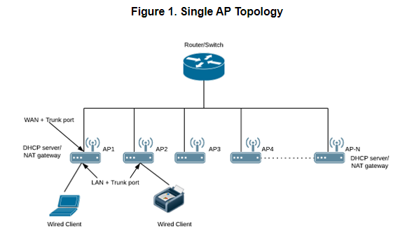
<div class="table-wrap"><table class="relative-table confluenceTable"><colgroup><col></col><col></col></colgroup><tbody><tr><td class="confluenceTd">## Single AP Topology

All the APs in the zone get their IP from the WAN router and provides the DHCP/NAT service. If H510/H320 is configured as GAP by the manual port selection, then LAN1 and LAN2 configuration will be pushed to eth1 and eth2 ports of H510/H320 APs instead of eth0 and eth1 ports.

Each AP in this zone is running it’s own DHCP server instance.  
Typically configured when APs are at different sites and roaming is not required.

</td><td class="confluenceTd">[![image.png](https://techblog.jcditservices.com/uploads/images/gallery/2024-08/scaled-1680-/6PPimage.png)](https://techblog.jcditservices.com/uploads/images/gallery/2024-08/6PPimage.png)

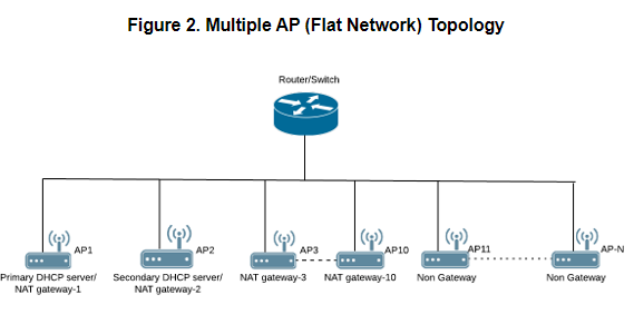
</td></tr><tr><td class="confluenceTd">## Multiple AP (Flat Network) Topology

All the APs in the zone get their IP from the WAN router and designated APs to provide the DHCP/NAT service. A maximum of two APs be can select for DHCP service (Primary and Secondary) and ten APs for NAT Gateway.

Designated APs in this zone are running the DHCP Server instance.  
Typically configured when multiple APs are at the same site and roaming across APs is needed.

</td><td class="confluenceTd">[![image.png](https://techblog.jcditservices.com/uploads/images/gallery/2024-08/scaled-1680-/HIximage.png)](https://techblog.jcditservices.com/uploads/images/gallery/2024-08/HIximage.png)

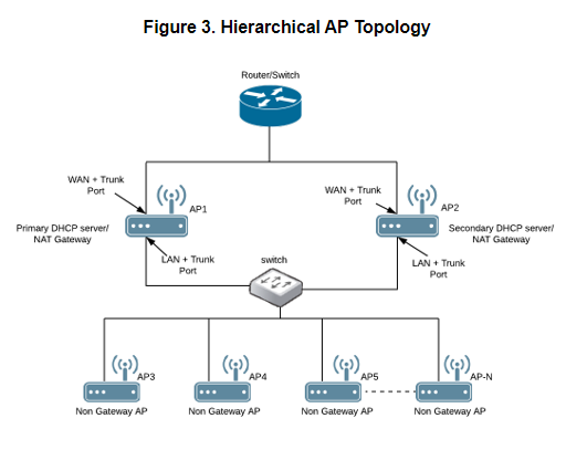
</td></tr><tr><td class="confluenceTd">## Hierarchical AP Topology

Designated APs provide the DHCP/NAT service. Gateway APs (GAPs) get the IP address from the WAN router and non-gateway APs get the IP from the Gateway APs. If H510/H320 is configured as GAP by the manual port selection, then LAN1 and LAN2 configuration will be pushed to eth1 and eth2 ports of H510/H320 APs instead of eth0 and eth1 ports. In order to configure eth0 ports of H510/H320, the user needs to configure LAN5/LAN3 Ports respectively for the H510/H320 APs.

Designated APs in this zone are running the DHCP Server instance.  
The DHCP server APs connected to the WAN, the rest of APs get their Private IP address from a local IP Pool with VLAN ID 1 from the DHCP Server AP.

</td><td class="confluenceTd">[![image.png](https://techblog.jcditservices.com/uploads/images/gallery/2024-08/scaled-1680-/05Pimage.png)](https://techblog.jcditservices.com/uploads/images/gallery/2024-08/05Pimage.png)

</td></tr></tbody></table>

</div></details><details id="bkmrk-method-login-to-the-"><summary>Method</summary>

Login to the vSZ and Navigate to **Services and Profiles** then **DHCP &amp; NAT**. Locate the domain under the organisation pane, then expand the required domain and highlight the zone you wish to configure your DHCP service. There will be an option to **Enable DHCP Service**. Enable this, to be directed through a configuration wizard.

[![image.png](https://techblog.jcditservices.com/uploads/images/gallery/2024-08/scaled-1680-/uO8image.png)](https://techblog.jcditservices.com/uploads/images/gallery/2024-08/uO8image.png)

Select the appropriate **Base Settings**. The options are **Single AP** (1), **Multiple APs** (&lt;12), or **Hierarchal APs** (&gt;12). For the purpose of this KB we will only be looking at **Single** **AP** or **Multiple AP** scenarios as Hierarchal will require a data plane. Click **Next** to continue.

[![image.png](https://techblog.jcditservices.com/uploads/images/gallery/2024-08/scaled-1680-/iPpimage.png)](https://techblog.jcditservices.com/uploads/images/gallery/2024-08/iPpimage.png)

Create a **DHCP Pool** by clicking on the **+**. A new page will pop up. Simply enter the required information and click **OK**. Repeat more networks if necessary. Once done, highlight and move the Pools from **Available Pools** to **Selected Pools** and click **Next** to continue.

[![image.png](https://techblog.jcditservices.com/uploads/images/gallery/2024-08/scaled-1680-/z9fimage.png)](https://techblog.jcditservices.com/uploads/images/gallery/2024-08/z9fimage.png)

[![image.png](https://techblog.jcditservices.com/uploads/images/gallery/2024-08/scaled-1680-/Cc9image.png)](https://techblog.jcditservices.com/uploads/images/gallery/2024-08/Cc9image.png)

[![image.png](https://techblog.jcditservices.com/uploads/images/gallery/2024-08/scaled-1680-/35Ximage.png)](https://techblog.jcditservices.com/uploads/images/gallery/2024-08/35Ximage.png)

On the next page, select your **Gateway AP(s).** The options are either **Automatic** or **Manual**. If you are selecting **Manual**, you will need to move AP(s) similar to moving the Pool(s) in the previous step and select a Primary and Secondary AP. Click **Next** to continue.

[![image.png](https://techblog.jcditservices.com/uploads/images/gallery/2024-08/scaled-1680-/Jpoimage.png)](https://techblog.jcditservices.com/uploads/images/gallery/2024-08/Jpoimage.png)

[![image.png](https://techblog.jcditservices.com/uploads/images/gallery/2024-08/scaled-1680-/RyJimage.png)](https://techblog.jcditservices.com/uploads/images/gallery/2024-08/RyJimage.png)

Review your configuration and click **OK** to confirm.

[![image.png](https://techblog.jcditservices.com/uploads/images/gallery/2024-08/scaled-1680-/T5kimage.png)](https://techblog.jcditservices.com/uploads/images/gallery/2024-08/T5kimage.png)

Configure your WLANs now as you normally would, however, ensure that under **Advanced Options** that your **Access VLAN** is set as per your DHCP profile.

[![image.png](https://techblog.jcditservices.com/uploads/images/gallery/2024-08/scaled-1680-/hmPimage.png)](https://techblog.jcditservices.com/uploads/images/gallery/2024-08/hmPimage.png)

Perform testing to ensure all is working as expected.

To prevent the two network users from being able to communicate with one another you must now create **L3 Access** **Control** profile(s). This will look something like the following:

*Action: Block*

*Source Network Address/Subnet Mask*

*Destination Network Address/Subnet Mask*

So for example, if we want to block communication between our Private and Guest wireless networks we will need to create two rules and affix these to the respective WLAN.

<u>*Block Guest on Private*</u>

*Action: Block*

*Source 192.168.66.0/24*

*Destination 192.168.99.0/24*

<u>*Block Private on Guest*</u>

*Action: Block*

*Source 192.168.99.0/24*

*Destination 192.168.66.0/24*

Navigate to **Firewall** then **L3 Access Control**, highlight the appropriate domain then click **Create**. A new page will pop up. Provide a **Name** and **Description** and create a rule by clicking **Create**. Add a **Description**, under **Access** select **Block** from the drop-down. Enter the **Source** and **Destination Network Address** and **Subnet Mask**. Set the **Direction** to **Dual**. Create profiles for any necessary networks.

[![image.png](https://techblog.jcditservices.com/uploads/images/gallery/2024-08/scaled-1680-/fbQimage.png)](https://techblog.jcditservices.com/uploads/images/gallery/2024-08/fbQimage.png)

[![image.png](https://techblog.jcditservices.com/uploads/images/gallery/2024-08/scaled-1680-/bHeimage.png)](https://techblog.jcditservices.com/uploads/images/gallery/2024-08/bHeimage.png)

Apply these to your WLANs by navigating to **Wireless LANs**, highlight and configure your WLAN, scroll down to **Firewall** and select the tickbox for **Enable WLAN specific**. Under the **L3 Access Control Policy** use the dropdown to select the appropriate profile. Repeat for all necessary WLANs.

[![image.png](https://techblog.jcditservices.com/uploads/images/gallery/2024-08/scaled-1680-/KwXimage.png)](https://techblog.jcditservices.com/uploads/images/gallery/2024-08/KwXimage.png)

Perform testing to ensure all is working as expected.

Notes

<div class="confluence-information-macro-body">- There is a limitation of 1000 IPs per DHCP Pool
- When running SMB **Multiple AP** mode, 10 IPs will be reserved for Gateway APs
- You can navigate to **Services and Profiles** then **DHCP &amp; NAT** to obtain information on the DHCP server stats

</div></details>

# How to Configure and Optimise SmartRoam on vSZ

<details id="bkmrk-introduction-some-cl"><summary>Introduction</summary>

Some clients do not roam even if they are physically moved to a new location. Not all clients have roaming aggressiveness setting to fine-tune roaming. Apple devices are reported to cling to the AP they first learn an SSID on.

In a multi-AP environment, a client will always be looking for the best AP to connect to. It will remain connected to its current AP and roam to an adjacent AP once the signal level falls below a certain threshold. This behavior ensures best possible performance at all times.  
  
To achieve this, a client must be doing background scanning to learn about its environment. Frequency of this background scan can determine the roaming behavior. Certain clients such as Windows clients allow roaming aggressiveness to be tweaked. "High" setting will make the client to perform background scanning more often to learn about available APs to connect. While the "Low" setting will make the client do less frequent scanning. This setting can be found under the wireless adapter properties.  
  
Unfortunately, this tweaking is not readily available for all client types. For example, various smartphones and Apple clients do not provide this setting to encourage roaming.  
  
For these types of clients, it is obvious to look towards infrastructure for help. Ruckus has added firmware support to disconnect a client if its signal falls below the user-definable threshold. This feature is called SmartRoam. With this feature, there will be an explicit disassociate message to kick off the client.

</details><details id="bkmrk-method-this-is-a-per"><summary>Method</summary>

This is a per-SSID setting as illustrated above. "smart-roam" parameter takes values from 1 to 10.  
These are called roam factors, and they map to an RSSI value in dB as per the list below:

[![image.png](https://techblog.jcditservices.com/uploads/images/gallery/2024-08/scaled-1680-/BXdimage.png)](https://techblog.jcditservices.com/uploads/images/gallery/2024-08/BXdimage.png)

The configuration can be changed from the CLI of the SmartZone.

**config  
domain "<span style="color: rgb(224, 62, 45);">Domain Name</span>"  
zone "<span style="color: rgb(224, 62, 45);">Zone Name</span>"  
wlan "<span style="color: rgb(224, 62, 45);">WLAN Name</span>"  
roam  
roam-factor 2.4g <span style="color: rgb(224, 62, 45);">x</span>  
roam  
roam-factor 5g <span style="color: rgb(224, 62, 45);">x</span>**

<span style="color: rgb(224, 62, 45);">***Red writing indicates a value that will be unique to your configuration. Note also that the quotes are required for parameters within a partner domain.***</span>

Additionally, if you enable DB Persistence event **209/218** on the vSZ you can see the system logs (events) for roaming activity.

[![image.png](https://techblog.jcditservices.com/uploads/images/gallery/2024-08/scaled-1680-/kxRimage.png)](https://techblog.jcditservices.com/uploads/images/gallery/2024-08/kxRimage.png)

[![image.png](https://techblog.jcditservices.com/uploads/images/gallery/2024-08/scaled-1680-/S4wimage.png)](https://techblog.jcditservices.com/uploads/images/gallery/2024-08/S4wimage.png)

</details>

# Advanced Guide: LDAP Authentication on Ruckus vSZ via Azure AD Domain Services (Azure AD DS)

Since **Ruckus Virtual SmartZone (vSZ) does not support SAML authentication** for admin logins, you must use **Azure AD Domain Services (Azure AD DS)** to provide an LDAP interface that vSZ can authenticate against.

Below is a more detailed breakdown, including user group mappings and troubleshooting.

---

### **1. Configure Azure AD Domain Services (Azure AD DS) for LDAP**

#### **Step 1: Enable Azure AD DS**

1. **Log in to Azure Portal**.
2. **Go to "Azure AD Domain Services" (AAD DS)** and create a **managed domain**:
    
    
    - Set the **DNS domain name** (e.g., `corp.yourcompany.local`).
    - Choose a **resource group** and **region**.
    - Select an **Azure Virtual Network (VNet)** (Ensure vSZ can reach this network).
3. **Synchronize Users from Azure AD to Azure AD DS**:
    
    
    - Azure AD DS automatically synchronizes users and groups from Azure AD.
    - Users must have **Kerberos and NTLM authentication enabled** (this is automatic for synced users).

#### **Step 2: Enable Secure LDAP (LDAPS)**

1. **Enable Secure LDAP** under **Azure AD DS &gt; Properties**.
2. **Download and install the SSL certificate** for LDAPS.
3. **Allow LDAP over SSL (TCP 636)** through your **Network Security Group (NSG)**.

#### **Step 3: Verify LDAP Access**

1. Run the following command from a machine that can reach Azure AD DS:
    
    <div class="contain-inline-size rounded-md border-[0.5px] border-token-border-medium relative bg-token-sidebar-surface-primary"><div class="sticky top-9"></div><div class="overflow-y-auto p-4" dir="ltr">`ldp.exe`</div></div>
2. Connect to **`yourdomain.local`** on **port 636**.
3. Bind using an Azure AD DS **admin account**.
4. If successful, LDAP is ready.

---

### **2. Configure LDAP Authentication on Ruckus vSZ**

#### **Step 1: Add an LDAP Server**

1. **Log in to vSZ Web UI**.
2. Navigate to **Administration &gt; AAA Servers**.
3. Click **Create** and select **LDAP**.
4. Fill in the LDAP server details:
    
    
    - **Server Address**: Enter the **IP Address of Azure AD DS**.
    - **Port**: `636` (for LDAPS).
    - **Bind DN**: A service account in Azure AD DS, e.g.: <div class="contain-inline-size rounded-md border-[0.5px] border-token-border-medium relative bg-token-sidebar-surface-primary"><div class="sticky top-9"></div><div class="overflow-y-auto p-4" dir="ltr">`<span class="hljs-attr">cn</span>=admin,ou=Users,dc=yourcompany,dc=local`</div></div>
    - **Password**: The service account's password.
    - **Base DN**: The starting point for LDAP searches, e.g.: <div class="contain-inline-size rounded-md border-[0.5px] border-token-border-medium relative bg-token-sidebar-surface-primary"><div class="sticky top-9"></div><div class="overflow-y-auto p-4" dir="ltr">`<span class="hljs-attr">dc</span>=yourcompany,dc=local`</div></div>
    - **User Attribute**: `sAMAccountName`
    - **SSL**: **Enable LDAPS**
    - **Certificate**: Upload the LDAPS certificate from Azure AD DS.
5. **Click Test Connection** to verify authentication.

---

### **3. Configure User Group Mappings**

Since Azure AD DS syncs groups from Azure AD, you can **map LDAP groups to Ruckus admin roles**.

#### **Step 1: Find LDAP Group DNs**

1. Run **`ldp.exe`** and connect to Azure AD DS.
2. Browse to **OU=Groups** to locate the full **Distinguished Name (DN)** of groups, e.g.: <div class="contain-inline-size rounded-md border-[0.5px] border-token-border-medium relative bg-token-sidebar-surface-primary"><div class="sticky top-9"></div><div class="overflow-y-auto p-4" dir="ltr">`<span class="hljs-attr">cn</span>=WiFiAdmins,ou=Groups,dc=yourcompany,dc=local`</div></div>

#### **Step 2: Assign LDAP Groups in vSZ**

1. **Go to "Administration &gt; Users &amp; Roles"**.
2. **Create a new User Group**.
3. **Select "Authentication Type: LDAP"**.
4. **Enter Group DN**, e.g.:
    
    <div class="contain-inline-size rounded-md border-[0.5px] border-token-border-medium relative bg-token-sidebar-surface-primary"><div class="sticky top-9"></div><div class="overflow-y-auto p-4" dir="ltr">`<span class="hljs-attr">cn</span>=WiFiAdmins,ou=Groups,dc=yourcompany,dc=local`</div></div>
5. Assign appropriate **permissions (e.g., System Admin, Read-Only Admin, etc.)**.
6. **Save and Apply**.

---

### **4. Troubleshooting LDAP Authentication on vSZ**

#### **Issue 1: LDAP Connection Fails**

- **Check firewall rules:** Allow **TCP 636** from vSZ to **Azure AD DS**.
- **Verify LDAPS certificate:** Upload it again if necessary.
- **Ensure service account has permissions** to query LDAP.

#### **Issue 2: Users Cannot Log In**

- **Confirm correct Base DN:** Run `ldp.exe` to verify the correct structure.
- **Ensure correct user attribute (`sAMAccountName`)** in vSZ settings.
- **Try logging in with UPN (`user@yourdomain.com`)** instead of the username.

#### **Issue 3: Group Mappings Do Not Work**

- Use **full group DN** (not just the group name).
- Ensure users are in the **correct group** in Azure AD DS.
- Run `ldapsearch` to manually verify group membership.

---

### **Final Thoughts**

Using **Azure AD DS with LDAPS** is the best way to integrate Azure authentication with **Ruckus Virtual SmartZone (vSZ)**. With proper **LDAP configuration and group mappings**, you can ensure **secure authentication** and centralized management.

# How to Configure and Optimise SmartRoam on vSZ

<details id="bkmrk-introduction-some-cl"><summary>Introduction</summary>

Some clients do not roam even if they are physically moved to a new location. Not all clients have roaming aggressiveness setting to fine-tune roaming. Apple devices are reported to cling to the AP they first learn an SSID on.

In a multi-AP environment, a client will always be looking for the best AP to connect to. It will remain connected to its current AP and roam to an adjacent AP once the signal level falls below a certain threshold. This behavior ensures best possible performance at all times.  
  
To achieve this, a client must be doing background scanning to learn about its environment. Frequency of this background scan can determine the roaming behavior. Certain clients such as Windows clients allow roaming aggressiveness to be tweaked. "High" setting will make the client to perform background scanning more often to learn about available APs to connect. While the "Low" setting will make the client do less frequent scanning. This setting can be found under the wireless adapter properties.  
  
Unfortunately, this tweaking is not readily available for all client types. For example, various smartphones and Apple clients do not provide this setting to encourage roaming.  
  
For these types of clients, it is obvious to look towards infrastructure for help. Ruckus has added firmware support to disconnect a client if its signal falls below the user-definable threshold. This feature is called SmartRoam. With this feature, there will be an explicit disassociate message to kick off the client.

</details><details id="bkmrk-method-%C2%A0"><summary>Method</summary>

This is a per-SSID setting as illustrated above. "smart-roam" parameter takes values from 1 to 10.  
These are called roam factors, and they map to an RSSI value in dB as per the list below:

[![image.png](https://techblog.jcditservices.com/uploads/images/gallery/2025-09/scaled-1680-/image.png)](https://techblog.jcditservices.com/uploads/images/gallery/2025-09/image.png)

The configuration can be changed from the CLI of the SmartZone.

**config  
domain "Domain Name"  
zone "Zone Name"  
wlan "WLAN Name"  
roam  
roam-factor 2.4g x  
roam  
roam-factor 5g x**

***Red writing indicates a value that will be unique to your configuration. Note also that the quotes are required for parameters within a partner domain.***

***x*** Defines the roam factor in the table above i.e. 1-10.

Remember to ensure configuration is saved.

Additionally, if you enable DB Persistence event **209/218** on the vSZ you can see the system logs (events) for roaming activity.

[![image.png](https://techblog.jcditservices.com/uploads/images/gallery/2025-09/scaled-1680-/Gplimage.png)](https://techblog.jcditservices.com/uploads/images/gallery/2025-09/Gplimage.png)

[![image.png](https://techblog.jcditservices.com/uploads/images/gallery/2025-09/scaled-1680-/T81image.png)](https://techblog.jcditservices.com/uploads/images/gallery/2025-09/T81image.png)

</details>

# Analytics

Ruckus Analytics

# Invite a 3rd Party to Ruckus Analytics

<details id="bkmrk-introduction-ruckus-"><summary>Introduction</summary>

RUCKUS Analytics is a cloud service for network intelligence and service assurance. Powered by machine learning and artificial intelligence, it gives IT comprehensive visibility into network operations. The service accelerates troubleshooting and helps IT teams meet their network SLAs. RUCKUS Analytics delivers powerful incident analytics, network health monitoring, advanced client troubleshooting and more.

This guide will help you create a **Resource Group**, then **Invite a 3rd Party** to manage said group.

</details><details id="bkmrk-managing-resource-gr"><summary>Managing Resource Groups</summary>

You can provide Role-Based Access Control (RBAC) to allow an administrator to manage APs and switches organized into resource groups.

A resource group is made up of your selection of APs and switches available in RUCKUS Analytics. There are many roles associated with resource groups with specific functional privileges. The roles available are Admin, Network Admin and Reporting. A resource group allows the Admin to confine access for a group of users to a restricted set of APs and switches. Therefore, a resource group is equivalent to a tenant.

RUCKUS Analytics contains a Default resource group. This group corresponds to the entire set of Wi-Fi assets. The Default resource group cannot be edited or deleted.

1. <span class="ph cmd" id="bkmrk-to-create-a-resource-1">To create a resource group of APs and switches, from the web interface, go to <span class="ph menucascade" id="bkmrk-admin%C2%A0%3E%C2%A0resource-gro"><span class="ph uicontrol" id="bkmrk-admin">Admin</span><abbr title="and then"> &gt; </abbr><span class="ph uicontrol" id="bkmrk-resource-groups">Resource Groups</span></span>. The <span class="keyword wintitle">Resource Groups</span> page is displayed.</span>
2. <span class="ph cmd" id="bkmrk-click%C2%A0create-resourc">Click <span class="ph uicontrol" id="bkmrk-create-resource-grou">Create Resource Group</span>.</span><div class="itemgroup stepresult" id="bkmrk-the%C2%A0create-resource-">The <span class="keyword wintitle">Create Resource Group</span> page is displayed.</div>Configure the following options: 
    - Name: Enter the name of the resource group that you are want to create. In this case, use the Customer Company Name
    - Description: Enter a short description about the group for reference.
    - Click the **AP** radio button and **Switch** radio button to view the devices within the network and domains. Choose the devices that you want by selecting the check-boxes, and click **<span class="ph uicontrol" id="bkmrk-create">Create</span>**. The resource group with the selected APs and switches is created and displayed in the **Resource Group** page.

</details><details id="bkmrk-inviting-users-and-a"><summary>Inviting Users and Assigning the Resource Group</summary>

You can add registered users, assign roles to the users, associate them to resource groups, and manage users from the <span class="ph" id="bkmrk-ruckus-analytics">RUCKUS Analytics</span> web interface.

<div class="section prereq p" id="bkmrk-the-user-must-be-reg">The user must be registered with the system.</div>1. <span class="ph cmd" id="bkmrk-from-the-web-interfa-1">From the web interface, go to <span class="ph menucascade" id="bkmrk-admin%C2%A0%3E%C2%A0users"><span class="ph uicontrol" id="bkmrk-admin-1">Admin</span><abbr title="and then"> &gt; </abbr><span class="ph uicontrol" id="bkmrk-users">Users</span></span>.</span>
2. <span class="ph cmd" id="bkmrk-add-third-party-user">Add third-party users by clicking <span class="ph uicontrol" id="bkmrk-invite-3rd-party">Invite 3rd Party</span>.</span>A third-party user is a user who does not belong to your organization. By inviting a third-party user, you are explicitly granting access to someone outside your organization to the <span class="ph" id="bkmrk-ruckus-analytics-1">RUCKUS Analytics</span> service account. Ensure that you have the necessary authorization to do so. A third-party user or a partner can only access a single resource group as defined by the administrator.
    
    <div class="itemgroup info" id="bkmrk-note%3A%C2%A0if-the%C2%A0admin%C2%A0r"><div class="note note note_note">  
    </div><div class="note note note_note" id="bkmrk-note%3A%C2%A0if-the%C2%A0admin%C2%A0r-1"><span class="note__title">Note:</span> If the **Admin** role is granted, the third-party user will also be able to invite other users into your account. If this is not desired, you can grant the third-party user a **Network Admin** or **Report Only** role. **Network Admin** is the preferred role for most deployments.</div><div class="note note note_note">  
    </div></div><div class="itemgroup info"><div class="itemgroup info">The <span class="keyword wintitle">Invite 3rd Party</span> dialog box is displayed where you can search for the user by their email ID. After typing the email ID, click <span class="ph uicontrol" id="bkmrk-find">Find</span>. Select the specific **Resource Group** and **Role** that you want the third-party user to be associated with and click <span class="ph uicontrol" id="bkmrk-invite">Invite</span>. **Network Admin** is the preferred role for most deployments.</div><div class="itemgroup info"><div class="note note note_note">  
    </div><div class="note note note_note" id="bkmrk-note%3A%C2%A0the-user-must-"><span class="note__title">Note:</span> The user must have a valid email ID that is registered with RUCKUS support. Else, the third-party account will be rendered invalid.</div><div class="note note note_note">  
    </div></div></div>Information relevant to the invitee is displayed in the <span class="keyword wintitle">Users </span>page. The user can accept or reject the invitation; the status of which is also displayed on this page as **Accepted**, **Rejected** or **Pending**. The user must also have a registered <span class="ph" id="bkmrk-ruckus-analytics-2">RUCKUS Analytics</span> account to accept the invitation. Additionally, only users having their own account with <span class="ph" id="bkmrk-ruckus-analytics-3">RUCKUS Analytics</span> can accept invitations. Else, they will not be granted permission to access the application. If the user wants to use another account to accept invitations, then the new account has to be added and registered with <span class="ph" id="bkmrk-ruckus-analytics-4">RUCKUS Analytics</span> before the user can accept invitation from that account.
    
    <div class="itemgroup info" id="bkmrk-"></div>
3. <span class="ph cmd" id="bkmrk-partners-or-third-pa">Partners or third party users who are invited to manage multiple customer accounts can take advantage of single sign-on by clicking on **Accounts** in the profile icon (top right). Partners can conveniently switch account views without having to re-login.</span>

</details>