MikroTik
MikroTik setup guides and tutorials
- Routers
- MikroTik hAP ax³ Setup Guide
- Creating an Option 43 Entry - Ruckus
- Setting Up Port Forwarding for IPSEC IKE Tunnel
- MikroTik Router Setup Guide with Multiple WAN Connections (SD-WAN) and VLAN Configuration
- Access Points
- Switches
- RouterOS
- Home and Office Setup Guides
- High Availability Solutions
Routers
Setup Guides for MikroTik Routers
MikroTik hAP ax³ Setup Guide
This guide will walk you through setting up a MikroTik hAP ax³ router with the following features:
- Two SSIDs: Home and Guest
- Three VLANs: Home, Guest, and IoT
- PPSK (Private Pre-Shared Key): Different keys for Home and IoT networks
- Firewall Rules: Optimized for streaming and gaming
Prerequisites
- MikroTik hAP ax³: Ensure your router is powered on and connected to your network.
- Winbox or Web Interface: Use Winbox or a web browser to access the router's management interface.
- Basic Network Setup: Have an existing internet connection.
Step-by-Step Setup
Step 1: Access MikroTik Router
- Open Winbox: Connect to your MikroTik router using Winbox or the web interface at
http://192.168.88.1. - Log in: Use the default username
adminand no password (change this immediately after login for security).
Step 2: Update RouterOS
Step 3: Create VLANs
Home VLAN
- Name: Home
- VLAN ID: 10
- Interface: Select the interface connected to your network.
Guest VLAN
- Name: Guest
- VLAN ID: 20
- Interface: Select the interface connected to your network.
IoT VLAN
- Name: IoT
- VLAN ID: 30
- Interface: Select the interface connected to your network.
Step 4: Configure Bridge and VLAN Filtering
Bridge Settings
- Name: bridge1
- Add VLANs to the Bridge:
- Go to Bridge > VLANs.
- Add each VLAN to the bridge with the respective VLAN ID and ports.
Step 5: Set Up Wireless Networks (SSIDs)
Home SSID
- Name: Home
- SSID: Home
- Security Profile: Create a new profile with WPA2-PSK.
- VLAN ID: 10
Guest SSID
- Name: Guest
- SSID: Guest
- Security Profile: Create a new profile with WPA2-PSK.
- VLAN ID: 20
- Configure PPSK for Home Network:
- Navigate to Wireless > Security Profiles.
- Create separate security profiles for each key associated with VLAN 10 and VLAN 30.
Step 6: Configure DHCP Servers
Home VLAN DHCP
- Interface: VLAN10
- Address Pool: Create an address pool for VLAN 10.
Guest VLAN DHCP
- Interface: VLAN20
- Address Pool: Create an address pool for VLAN 20.
IoT VLAN DHCP
- Interface: VLAN30
- Address Pool: Create an address pool for VLAN 30.
Step 7: Configure Firewall Rules
Allow Streaming Services
- Chain: forward
- Action: accept
- Src. Address List: Create an address list for streaming services.
Allow Gaming Services
- Chain: forward
- Action: accept
- Src. Address List: Create an address list for gaming services.
Deny Other Traffic
- Chain: forward
- Action: drop
- Log: enabled (for troubleshooting purposes).
- Prioritize Traffic:
- Use Mangle rules to mark packets from specific devices and apply Queue Trees to prioritize gaming and streaming traffic.
Step 8: Test the Configuration
- Connect devices to the Home and Guest SSIDs.
- Test connectivity to ensure devices are assigned to the correct VLANs.
- Verify streaming and gaming performance to ensure traffic is prioritized correctly.
Additional Tips
- Secure Access: Change the default admin password and secure management access.
- Regular Backups: Save your configuration regularly to avoid data loss.
- Firmware Updates: Keep your RouterOS and firmware up-to-date for security and performance.
https://mikrotik.com/product/hap_ax3
Creating an Option 43 Entry - Ruckus
Introduction
This option is used by clients and servers to exchange vendor-specific information. Servers that are not equipped to interpret the information ignore it. Clients that expect but don't receive the information attempt to operate without it.
Option 43 can be especially helpful for pointing Ruckus access points to controller (ZoneDirector or SCG/SZ). The resolution to configure Option 43 is explained below.
Method - Obtaining your Value
You will need to know the following prefix both ZoneDirector(s) and SmartCell Gateway/SmartZone(s).
- Zone Director: 0x30c
- SCG/SZ: 0x60c or 0x60f
You will also need to convert the ASCII text of your controller IP address to HEX. I use the following site for converting but feel free to use whichever you like.
An example of the HEX converter:
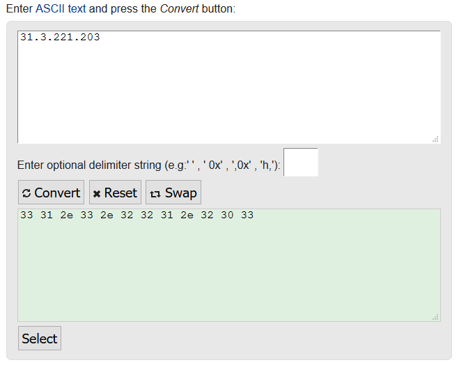
Putting these together will give you your 'value'. For example:
To point a Ruckus AP to a SCG/SZ to example IP 31.3.221.203 would be: 0x60c + 33312e332e3232312e323033 = 0x60c33312e332e3232312e32303
To point a Ruckus AP to a ZD to IP 192.168.1.1 would be: 0x30c + 3139322e3136382e312e31 = 0x30c3139322e3136382e312e31
Method - Setting this in the MikroTik
For the purpose of this article I will assume you have a minimal/basic understanding of the device and know how to login to the MikroTik device.
Open your MikroTik router in Winbox or Webfig. Browse to: IP > DHCP Server > Options > Click the blue '+' to create a new profile
Provide the following:
- Name: Defined by yourself
- Code: This MUST be 43
- Value: Defined by your obtained value
Click 'Apply' and then 'OK'.
This then needs to be applied too your network address. To do this go to: IP > DHCP Server > Networks > Double click the network required (the ones which your AP's will be on) > On DHCP Options click the dropdown and select the profile.
Any AP's now connected to this network should be pointed towards the controller, and appear in their Staging Zone or on the ZD pending any auto provision rules setup on the controller.
Setting Up Port Forwarding for IPSEC IKE Tunnel
Introduction
- Port forwarding, also known as tunnelling, is a network technology procedure that enables external devices to access services on a private network. This is achieved by rerouting communication requests from one address and port number combination to another while packets traverse a network gateway.
- It is extensively used in scenarios where certain applications or services need to be accessible from the internet, including online gaming, torrent downloads, and hosting web servers. These applications typically require direct communication with devices on your private network, which isn’t possible due to NAT (Network Address Translation) mechanisms used by most routers.
- While port forwarding can grant outside access and improve connectivity, it also presents a potential risk as it exposes your internal network to the internet. As such, it’s crucial to exercise due caution by only forwarding necessary ports and implementing robust security measures such as using strong, complex passwords and up-to-date firewall settings.
Method
Step 1: Access MikroTik Router
- Open Winbox or your web browser and connect to your MikroTik router.
- Log in using your credentials.
Step 2: Configure Port Forwarding
- Go to IP > Firewall > NAT.
- Click on the + to add a new rule.
1. Port Forwarding for UDP Port 500 (IKE)
- General Tab:
- Chain: dstnat
- Protocol: udp
- Dst. Port: 500 (this may change, request from the client what is needed. Also ensure that it does not interfere with any existing ports configured)
- Action Tab:
- Action: dst-nat
- To Addresses: Internal IP address (e.g., 192.168.1.2)
- To Ports: 500 (this may change, request from the client what is needed. Also ensure that it does not interfere with any existing ports configured)
2. Port Forwarding for UDP Port 4500 (NAT-T)
- General Tab:
- Chain: dstnat
- Protocol: udp
- Dst. Port: 4500 (this may change, request from the client what is needed. Also ensure that it does not interfere with any existing ports configured)
- Action Tab:
- Action: dst-nat
- To Addresses: Internal IP address (e.g., 192.168.1.2)
- To Ports: 4500 (this may change, request from the client what is needed. Also ensure that it does not interfere with any existing ports configured)
Step 3: Configure Firewall Rules
- Go to IP > Firewall > Filter Rules.
- Click on the + to add new rules.
1. Allow UDP Port 500 (IKE)
- General Tab:
- Chain: forward
- Protocol: udp
- Dst. Port: 500 (this may change, request from the client what is needed. Also ensure that it does not interfere with any existing ports configured)
- Action Tab:
- Action: accept
2. Allow UDP Port 4500 (NAT-T)
- General Tab:
- Chain: forward
- Protocol: udp
- Dst. Port: 4500 (this may change, request from the client what is needed. Also ensure that it does not interfere with any existing ports configured)
- Action Tab:
- Action: accept
Step 4: Sort the Filter Rules
- Drag and drop the filter rules you have created in Step 3 so that they are above any existing 'drop rules'.
Step 5: Ensure IP Forwarding is Enabled
- Go to IP > Settings.
- Make sure IP Forwarding is enabled.
Step 6: Verify Configuration
- Check the NAT Rules:
- Ensure the NAT rules are correctly set up and active.
- Go to IP > Firewall > NAT and verify that the new rules are listed and active.
- Check the Firewall Rules:
- Ensure the firewall rules are correctly set up and active.
- Go to IP > Firewall > Filter Rules and verify that the new rules are listed and active.
- Test the VPN Connection:
- Attempt to establish the VPN connection from the internal router to Azure.
- Verify the connection by checking the VPN status on the internal router.
MikroTik Router Setup Guide with Multiple WAN Connections (SD-WAN) and VLAN Configuration
This guide will help you configure your MikroTik router with the following features:
- Introduction to Multiple WAN Connections (SD-WAN)
- Three WAN Connections: Fiber (Primary), 5G, and Starlink
- Load Balancing and Failover: Prioritize Fiber connection
- Three VLANs: Home, Guest, and IoT
- Firewall Rules: Optimized for streaming and gaming
- Traffic Prioritization: Using Quality of Service (QoS)
Prerequisites
- MikroTik Router: Ensure your device supports the necessary features (e.g., RB4011, CCR series).
- Access to Router Management Interface: Use Winbox or WebFig to configure the router.
- WAN Connections: Have your Fiber, 5G, and Starlink connections physically connected to the router.
- Basic Network Knowledge: Familiarity with network configurations and terms.
Step-by-Step Setup
Step 1: Access the MikroTik Router
- Connect to the Router: Use an Ethernet cable to connect your computer to the router.
- Open Winbox: Download from the MikroTik website if you haven't already.
- Login:
- MAC Address: Use the MAC address to connect if the IP is not set.
- Default Username:
admin - Default Password: (Leave blank initially; change immediately for security)
Step 2: Configure WAN Interfaces
Identify the interfaces connected to your WAN connections.
Assign Names to WAN Interfaces
- Fiber Connection (Primary)
- Interface: e.g.,
ether1 - Name:
WAN_Fiber
- Interface: e.g.,
- 5G Connection
- Interface: e.g.,
ether2 - Name:
WAN_5G
- Interface: e.g.,
- Starlink Connection
- Interface: e.g.,
ether3 - Name:
WAN_Starlink
- Interface: e.g.,
Configure IP Addresses for WAN Interfaces
- Go to:
IP > DHCP Client - Add DHCP Client for each WAN interface:
- Interface:
WAN_Fiber - Use Peer DNS: Yes
- Add Default Route: No (We'll set routes manually)
- Repeat for
WAN_5GandWAN_Starlink
- Interface:
Step 3: Configure Load Balancing and Failover
We'll set up routing rules to prioritize the Fiber connection and use the 5G and Starlink as backups.
Set Default Routes with Different Distances
- Go to:
IP > Routes - Add Route for Fiber Connection
- Destination Address:
0.0.0.0/0 - Gateway: Select the gateway provided by the DHCP client on
WAN_Fiber(e.g.,WAN_Fiberinterface) - Distance:
1(Primary connection)
- Destination Address:
- Add Route for 5G Connection
- Destination Address:
0.0.0.0/0 - Gateway: Select the gateway from
WAN_5G - Distance:
2
- Destination Address:
- Add Route for Starlink Connection
- Destination Address:
0.0.0.0/0 - Gateway: Select the gateway from
WAN_Starlink - Distance:
3
- Destination Address:
Set Up Check Gateway
- Edit Each Route: Enable
Check Gatewaywithpingto monitor the connection.- This allows the router to detect when a connection is down and automatically switch to the next available connection.
Step 4: Configure VLANs
Create VLAN Interfaces
- Go to:
Interfaces - Click:
+(Add New Interface)- Type:
VLAN
- Type:
Home VLAN
- Name:
VLAN_Home - VLAN ID:
10 - Interface: Physical interface connected to your switch (e.g.,
ether5)
Guest VLAN
- Name:
VLAN_Guest - VLAN ID:
20 - Interface:
ether5
IoT VLAN
- Name:
VLAN_IoT - VLAN ID:
30 - Interface:
ether5
Configure Bridge Interface
If using multiple VLANs on a single physical interface, it's good practice to use a bridge.
- Go to:
Bridge - Add New Bridge
- Name:
BR_LAN
- Name:
- Add Ports to Bridge
- Go to:
Bridge > Ports - Add:
ether5toBR_LAN - Add:
VLAN_Home,VLAN_Guest,VLAN_IoTtoBR_LAN
- Go to:
Assign IP Addresses to VLAN Interfaces
- Go to:
IP > Addresses - Add New Address
Home VLAN
- Address:
192.168.10.1/24 - Interface:
VLAN_Home
Guest VLAN
- Address:
192.168.20.1/24 - Interface:
VLAN_Guest
IoT VLAN
- Address:
192.168.30.1/24 - Interface:
VLAN_IoT
Step 5: Configure DHCP Servers for Each VLAN
- Go to:
IP > DHCP Server - Click:
DHCP Setup
Home VLAN DHCP
- Interface:
VLAN_Home - Follow the prompts to set:
- Address Pool:
192.168.10.2-192.168.10.254 - Gateway:
192.168.10.1 - DNS Servers: Use your preferred DNS (e.g.,
8.8.8.8)
- Address Pool:
Guest VLAN DHCP
- Interface:
VLAN_Guest - Address Pool:
192.168.20.2-192.168.20.254 - Gateway:
192.168.20.1 - DNS Servers:
8.8.8.8
IoT VLAN DHCP
- Interface:
VLAN_IoT - Address Pool:
192.168.30.2-192.168.30.254 - Gateway:
192.168.30.1 - DNS Servers:
8.8.8.8
Step 6: Configure Firewall Rules
MikroTik uses a default firewall configuration; we'll modify it to suit our needs.
Enable NAT for Internet Access
- Go to:
IP > Firewall > NAT - Add New NAT Rule
- Chain:
srcnat - Out Interface List:
WAN(We'll create an interface list for WAN interfaces) - Action:
masquerade
- Chain:
Create Interface List for WAN
- Go to:
Interfaces > Interface List - Add New List
- Name:
WAN - Add Interfaces:
WAN_Fiber,WAN_5G,WAN_Starlink
- Name:
Allow Traffic from VLANs to WAN
- Go to:
IP > Firewall > Filter Rules - Add New Rule
- Chain:
forward - Src. Address:
192.168.10.0/24,192.168.20.0/24,192.168.30.0/24 - Out Interface List:
WAN - Action:
accept
- Chain:
Drop Inter-VLAN Traffic
- Add New Rule
- Chain:
forward - Src. Address List: Create an address list for your VLAN subnets.
- Name:
VLAN_Networks - Addresses:
192.168.10.0/24,192.168.20.0/24,192.168.30.0/24
- Name:
- Dst. Address List:
VLAN_Networks - Action:
drop - Place this rule before the rule that accepts established/related traffic.
- Chain:
Allow Established and Related Traffic
- Ensure you have a rule to accept established and related connections
- Chain:
forward - Connection State:
established, related - Action:
accept
- Chain:
Drop Invalid Traffic
- Add Rule
- Chain:
forward - Connection State:
invalid - Action:
drop
- Chain:
Step 7: Configure Traffic Prioritization (QoS)
We'll use Simple Queues to prioritize gaming and streaming traffic.
Identify Gaming and Streaming Traffic
-
Go to:
IP > Firewall > Mangle -
Add New Rule for Gaming Traffic
- Chain:
forward - Protocol: Select protocols used by games (e.g., TCP/UDP ports)
- Dst. Port: Add known gaming ports
- Action:
mark-packet - New Packet Mark:
Gaming_Traffic - Passthrough:
yes
- Chain:
-
Add New Rule for Streaming Traffic
- Chain:
forward - Dst. Address List: Create an address list for streaming services (e.g., Netflix IP ranges)
- Action:
mark-packet - New Packet Mark:
Streaming_Traffic - Passthrough:
yes
- Chain:
Create Simple Queues
- Go to:
Queues > Simple Queues
Gaming Traffic Queue
- Name:
Priority_Gaming - Target:
192.168.10.0/24(Assuming gaming devices are on the Home VLAN) - Max Limit: Set according to your bandwidth
- Limit At: Set minimum guaranteed bandwidth
- Priority:
1(Highest priority) - Advanced Tab:
- Packet Marks:
Gaming_Traffic
- Packet Marks:
Streaming Traffic Queue
- Name:
Priority_Streaming - Target:
192.168.10.0/24 - Max Limit: Set according to your bandwidth
- Limit At: Set minimum guaranteed bandwidth
- Priority:
2 - Advanced Tab:
- Packet Marks:
Streaming_Traffic
- Packet Marks:
Step 8: Secure the Router
Change the Default Admin Password
- Go to:
System > Users - Edit:
admin - Set a strong password
Disable Unnecessary Services
- Go to:
IP > Services - Disable services you don't use (e.g., FTP, Telnet)
- Ensure Winbox and SSH are secured
Enable HTTPS for WebFig
- Go to:
IP > Services - Enable:
www-ssl - Disable:
www(HTTP)
Step 9: Test the Configuration
- VLAN Connectivity: Connect devices to each VLAN and ensure they receive the correct IP addresses.
- Internet Access: Verify that devices can access the internet.
- Failover: Disconnect the Fiber connection to test if traffic fails over to 5G or Starlink.
- Load Balancing: Monitor traffic using
Tools > Torchto see if load balancing works as expected. - QoS Effectiveness: Use bandwidth-intensive applications to test if gaming and streaming traffic are prioritized.
Additional Tips
- Regular Backups: Go to
Files, select your configuration file, and download it to your computer. - Firmware Updates: Check
System > Packagesfor updates and upgrade to the latest stable version. - Monitor Traffic: Use
Tools > GraphingorQueues > Queue Treeto monitor bandwidth usage. - Logs: Check
Logfor any errors or unusual activity.
By following this guide, you should have a MikroTik router configured with multiple WAN connections, VLAN segmentation, firewall rules, and QoS prioritization. The Fiber connection is set as the primary WAN, with 5G and Starlink serving as backup connections to ensure uninterrupted internet access.
Note: MikroTik routers are highly versatile but can be complex. Always make sure to back up your configuration before making significant changes, and consult the MikroTik Wiki or Forums if you encounter issues.
Access Points
MikroTik Access Points and Setup Guides
Switches
MikroTik switches , setup guides for RouterOS and SwitchOS
RouterOS
Information Regarding MikroTik RouterOS
Branding Maker
Introduction
RouterOS allows slight system customization with the help of a branding package. This is a special system package, which you can generate from within your mikrotik.com account, in the account section "Branding maker". The resulting file will have a .dpk extension and can be installed by all the same means as an .npk package. The generated package can be installed in any RouterOS version. To install the package in a device you simply need to upload it and reboot the router, you can also use Netinstall tool for the same effect.
ASCII logo
This is the text logo shown when logging into the command line interface, i.e. Telnet, SSH, Winbox Terminal. The ASCII logo you can create right there in the browser, or copy from any other plaintext editor. Make sure it is not wider than the form in the branding maker page, or your logo will be distorted.
Default webpage
You can customize the default RouterOS information page, which shows up when accessing the router IP address, and a password is set on the device. When making the HTML file, you can use these variables:
- %version% will change to the router's current version
- %host% will change to the router's IP address. Use these variables in the Telnet link, or in the header.
The file must be named "index2.html". Make sure you use properly nested HTML to make your page compatible with all browsers. You can also upload images or JavaScript files, they must reference to the same path as the index file, no custom folder names can be used.If you wish to only change the MikroTik logo, and not upload the whole HTML file, the name of the default image is mikrotik_logo.png, uploading another file with the same name, will overwrite the original. Other values
- Router name: this is the Identity value in RouterOS, it can only be one word, don't use spaces or special characters there.
- Company URL: this is the value that appears in the console when you connect to your MikroTik device.
- Manual URL: documentation link which opens with a button in Webfig in the web interface.
- LCD logo: this will be displayed on devices equipped with LCD screen. Requirements for logo: no more than 160px width and no more than 72px height. CCR series have white (0xffffff) background, 2011 series have black (0x000000) background.
- Default configuration: Note that when using the default configuration file, the configuration is appended when simply installing the package, but after using system reset, only the configuration in your file will be used, all other standard default config will not be used during reset. The file must be a text/rsc file with one RouterOS command per line. You can use an export file from the console as a starting point, but we recommend only leaving the exact commands you want to run. This configuration will be kept even after the RouterOS reset.
- Skins: For skins, a file your_file_name.json must be uploaded into the "skins" directory.
In order to apply particular skin to a specific user group, you don't need to log into the router to do that. You can do it with branding by uploading a Default configuration file.
Or set the skin for the user group manually after reboot.
- Custom files: RouterOS 6.48.3 and above also supports uploading of custom files, they will be simply copied into a folder named "branding" and will be accessible from within RouterOS.
Method
You must first log in to a MikroTik account: https://mikrotik.com/client/login. If you do not have one, you can register here: https://mikrotik.com/client/register
From the main menu/dashboard, navigate to OTHER/Branding Maker. This will load up the configurator. Expand and ensure you read the +Read this first! section to fully understand the parameters.
Enter a Router Name, Company URL, Manual URL and Telnet ASCII Logo. Click Make once you are happy. You will then need to make for either version 6.47 and above or make for an older version.
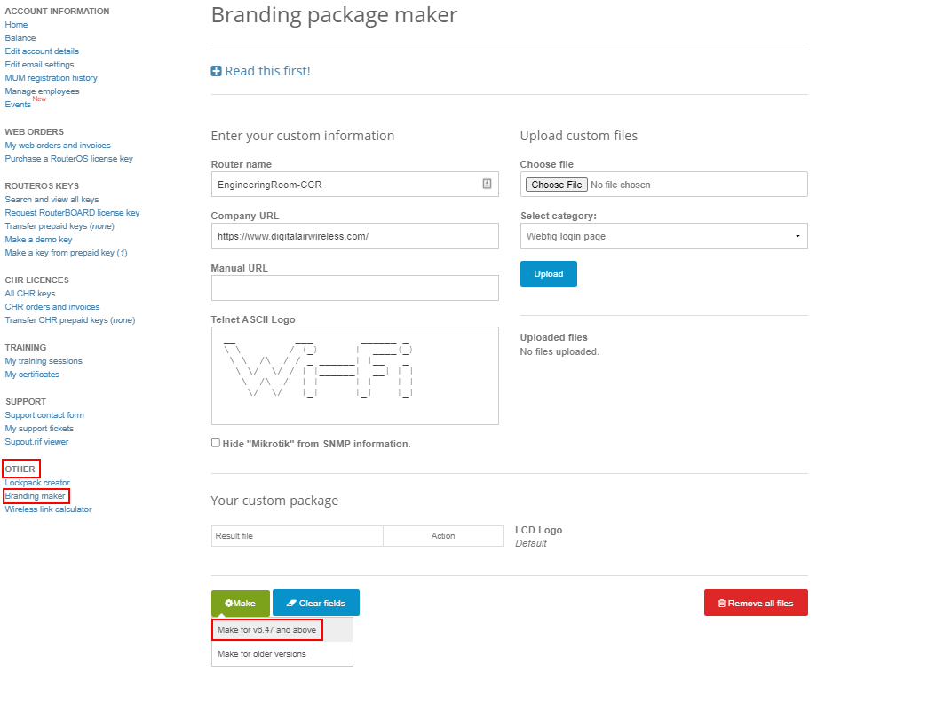
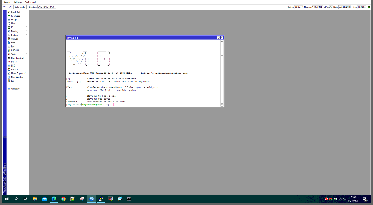
The generated package can be installed in any RouterOS version.
The ASCII logo above you can create right here in the browser, or copy from any other plaintext editor. Make sure it is not wider than the form above, or your logo will be distorted.
Then making the HTML file, you can use different kinds of variables. For example %version% will change to the router's current version. %host% will change to the router's IP address. Use these variables in the Telnet link, or in the header.
The "Router name" is actually the Identity in RouterOS, it can only be one word, don't use spaces or special characters there.
LCD logo will be displayed on devices equipped with LCD screens.
Requirements for logo: no more than 160px width and no more than 72px height.
CCR series have white (0xffffff) background, 2011 series have black (0x000000) background.
Note that when using the default configuration file, the configuration is appended when simply installing the package, but after using system reset, only the configuration in your file will be used, all other standard default config will not be used during reset.
To install the package on a device you simply need to upload it and reboot the router, you can also use Netinstall tool for the same effect.
To create a complete branding package, you need to upload the following files:
- The main HTML file will appear when entering the router's IP address in a web browser. The file must be named "index2.html". Make sure you use properly nested HTML to make your page compatible with all browsers.
- The images and other files are associated with this file.
- You can also upload just the router web page logo, which should be named "mikrotik_logo.png".
- The Hotspot login page logo, the file must be named "logobottom.png",
- For skins, a file default.json must be uploaded into the "skins" directory.
- For RouterOS default configuration, a text/rsc file with one RouterOS command per line. You can use an export file from the console. This configuration will be kept even after the RouterOS reset.
Home and Office Setup Guides
Various MikroTik Setup guides for Home and Office deployments
Home Office Network Setup Guide
Below is a MikroTik configuration tailored to your requirements.
This configuration includes:
- 4 VLANs: Home (VLAN 10), Office (VLAN 20), Guest (VLAN 30), and IoT (VLAN 40).
- Subnetting: Each VLAN uses the
10.x.x.x/24subnet, with the subnet identifier matching the VLAN ID. - Firewall Rules: Home and Office VLANs can access the IoT VLAN; IoT and Guest VLANs are isolated from other VLANs.
- Security Enhancements: Hardened router security with essential services only and restricted management access.
1. Bridge and VLAN Setup
Create a Bridge Interface with VLAN Filtering
/interface bridge
add name=bridge1 vlan-filtering=yes
Add Physical Ports to the Bridge
Assuming ether2 to ether5 are your LAN ports:
/interface bridge port
add bridge=bridge1 interface=ether2 pvid=10
add bridge=bridge1 interface=ether3 pvid=20
add bridge=bridge1 interface=ether4 pvid=30
add bridge=bridge1 interface=ether5 pvid=40
Define VLANs on the Bridge
/interface bridge vlan
add bridge=bridge1 tagged=bridge1 untagged=ether2 vlan-ids=10
add bridge=bridge1 tagged=bridge1 untagged=ether3 vlan-ids=20
add bridge=bridge1 tagged=bridge1 untagged=ether4 vlan-ids=30
add bridge=bridge1 tagged=bridge1 untagged=ether5 vlan-ids=40
Create VLAN Interfaces
/interface vlan
add interface=bridge1 name=VLAN10 vlan-id=10
add interface=bridge1 name=VLAN20 vlan-id=20
add interface=bridge1 name=VLAN30 vlan-id=30
add interface=bridge1 name=VLAN40 vlan-id=40
2. IP Addressing
Assign IP addresses to each VLAN interface, matching the subnet with the VLAN ID:
/ip address
add address=10.10.10.1/24 interface=VLAN10 network=10.10.10.0
add address=10.10.20.1/24 interface=VLAN20 network=10.10.20.0
add address=10.10.30.1/24 interface=VLAN30 network=10.10.30.0
add address=10.10.40.1/24 interface=VLAN40 network=10.10.40.0
3. DHCP Server Configuration
Create IP Pools for Each VLAN
/ip pool
add name=dhcp_pool_vlan10 ranges=10.10.10.10-10.10.10.254
add name=dhcp_pool_vlan20 ranges=10.10.20.10-10.10.20.254
add name=dhcp_pool_vlan30 ranges=10.10.30.10-10.10.30.254
add name=dhcp_pool_vlan40 ranges=10.10.40.10-10.10.40.254
Set Up DHCP Servers
/ip dhcp-server
add address-pool=dhcp_pool_vlan10 interface=VLAN10 lease-time=12h name=dhcp_vlan10
add address-pool=dhcp_pool_vlan20 interface=VLAN20 lease-time=12h name=dhcp_vlan20
add address-pool=dhcp_pool_vlan30 interface=VLAN30 lease-time=12h name=dhcp_vlan30
add address-pool=dhcp_pool_vlan40 interface=VLAN40 lease-time=12h name=dhcp_vlan40
Define DHCP Networks
/ip dhcp-server network
add address=10.10.10.0/24 dns-server=8.8.8.8,8.8.4.4 gateway=10.10.10.1
add address=10.10.20.0/24 dns-server=8.8.8.8,8.8.4.4 gateway=10.10.20.1
add address=10.10.30.0/24 dns-server=8.8.8.8,8.8.4.4 gateway=10.10.30.1
add address=10.10.40.0/24 dns-server=8.8.8.8,8.8.4.4 gateway=10.10.40.1
4. Firewall Configuration
Basic Firewall Rules
- Accept established and related connections.
- Drop invalid packets.
/ip firewall filter
add chain=forward connection-state=established,related action=accept
add chain=forward connection-state=invalid action=drop
Inter-VLAN Communication Rules
- Allow Home and Office VLANs to access the IoT VLAN.
add chain=forward src-address=10.10.10.0/24 dst-address=10.10.40.0/24 action=accept
add chain=forward src-address=10.10.20.0/24 dst-address=10.10.40.0/24 action=accept
- Allow Home and Office VLANs to access the internet.
add chain=forward src-address=10.10.10.0/24 action=accept out-interface-list=WAN
add chain=forward src-address=10.10.20.0/24 action=accept out-interface-list=WAN
Restrict IoT and Guest VLANs
- Drop traffic from IoT VLAN to other VLANs.
add chain=forward src-address=10.10.40.0/24 dst-address=10.10.10.0/24 action=drop
add chain=forward src-address=10.10.40.0/24 dst-address=10.10.20.0/24 action=drop
add chain=forward src-address=10.10.40.0/24 dst-address=10.10.30.0/24 action=drop
- Drop traffic from Guest VLAN to other VLANs.
add chain=forward src-address=10.10.30.0/24 dst-address=10.10.10.0/24 action=drop
add chain=forward src-address=10.10.30.0/24 dst-address=10.10.20.0/24 action=drop
add chain=forward src-address=10.10.30.0/24 dst-address=10.10.40.0/24 action=drop
- Allow IoT and Guest VLANs to access the internet.
add chain=forward src-address=10.10.40.0/24 action=accept out-interface-list=WAN
add chain=forward src-address=10.10.30.0/24 action=accept out-interface-list=WAN
Drop All Other Traffic
add chain=forward action=drop
5. NAT Configuration
Ensure that all VLANs can access the internet:
/ip firewall nat
add chain=srcnat out-interface-list=WAN action=masquerade
6. Security Hardening
Restrict Router Access
- Allow management access only from Home and Office VLANs.
/ip firewall filter
add chain=input connection-state=established,related action=accept
add chain=input connection-state=invalid action=drop
add chain=input src-address=10.10.10.0/24 action=accept
add chain=input src-address=10.10.20.0/24 action=accept
add chain=input action=drop
Disable Unnecessary Services
/ip service
set telnet disabled=yes
set ftp disabled=yes
set www disabled=yes
set ssh disabled=yes
set api disabled=yes
set api-ssl disabled=yes
set winbox address=10.10.10.0/24,10.10.20.0/24
Note: Only Winbox is enabled for management, and access is restricted to Home and Office VLANs.
Set Strong Passwords
Ensure the router's admin password is strong:
/user set 0 name=admin password=YourStrongPassword
Replace YourStrongPassword with a strong, unique password.
Additional Security Measures
- System Updates: Regularly update your router's firmware to the latest stable version.
- Backup Configuration: Keep backups of your configuration in a secure location.
- Logging: Enable system logging for monitoring.
7. Final Notes
- Adjust Interface Names: Replace
ether2,ether3, etc., with your actual interface names if they differ. - WAN Interface: Ensure your WAN interface is added to the
WANinterface list.
/interface list
add name=WAN
/interface list member
add interface=ether1 list=WAN
Assuming ether1 is your WAN interface.
- DNS Servers: You can replace
8.8.8.8,8.8.4.4with your preferred DNS servers. - Safe Mode: When applying configurations, use Safe Mode in Winbox or CLI to prevent lockouts.
By implementing this configuration, you'll have a secure and segmented network that meets your home office needs.
High Availability Solutions
- Load Balancing
- Bonding
- Bonding Examples
- HA Case Studies
- Multi-chassis Link Aggregation Group
- VRRP
- VRRP Configuration Examples
Load Balancing
Introduction
Network load balancing is the ability to balance traffic across two or more links without using dynamic routing protocols.
There are two type of balancing methods:
- per-packet - each packet of a single stream can be forwarded over different links. This method will work reliably especially on TCP and secure connections only when you are able to control both balancing endpoints.
- per-connection - all packets of the same connection (stream) is always sent over one link. This method is mandatory in setups where only one end of the balancing is under our control, for example, home router with multiple WAN connections.
| Method | Per-connection | Per-packet | |
|---|---|---|---|
|
Firewall Mangle |
Nth | Yes | Yes |
| PCC (Per Connection Classifier) | Yes | No | |
| Other matchers | Yes | Yes | |
| ECMP (Equal Cost Multi-Path) | Yes | No | |
| Bonding | No | Yes | |
| OSPF | Yes | No | |
| BGP | Yes | No | |
Simple Failover Example
Simplest failover setup would be to use multiple gateways when one gateway is active and another one takes over when the first one fails.
To make this work, configure larger distance value for the secondary one, and check-gateway for the first one:
/ip route add gateway=192.168.1.1 distance=1 check-gateway=ping /ip route add gateway=192.168.2.1 distance=2The check-gateway will make sure the gateway is up only when actual traffic can reach the gateway. When the ping fails the first gateway will become inactive and the second one will take over, and when the first gateway recovers it will become active and make the second gateway to work again as a backup.
Per connection classifier
PCC matcher will allow you to divide traffic into equal streams with the ability to keep packets with specific set of options in one particular stream (you can specify this set of options from src-address, src-port, dst-address, dst-port)
Theory
PCC takes selected fields from IP header, and with the help of a hashing algorithm converts selected fields into 32-bit value. This value then is divided by a specified Denominator and the remainder then is compared to a specified Remainder, if equal then the packet will be captured. You can choose from src-address, dst-address, src-port, dst-port from the header to use in this operation.
PCC is not a valid method, in case of Hotspot(captive portal) - due to the fact that Hotspot uses web-proxy and it uses only the default routing table, at the moment.
per-connection-classifier=
PerConnectionClassifier ::= [!]ValuesToHash:Denominator/Remainder
  Remainder ::= 0..4294967295    (integer number)
  Denominator ::= 1..4294967295    (integer number)
  ValuesToHash ::= both-addresses|both-ports|dst-address-and-port|
  src-address|src-port|both-addresses-and-ports|dst-address|dst-port|src-address-and-port
Example
This configuration will divide all connections into 3 groups based on the source address and port
/ip firewall mangle add chain=prerouting action=mark-connection \
 new-connection-mark=1st_conn per-connection-classifier=src-address-and-port:3/0
/ip firewall mangle add chain=prerouting action=mark-connection \
  new-connection-mark=2nd_conn per-connection-classifier=src-address-and-port:3/1
/ip firewall mangle add chain=prerouting action=mark-connection \
  new-connection-mark=3rd_conn per-connection-classifier=src-address-and-port:3/2
How PCC works
This article aims to explain in simple terms how PCC works. The definition from the official manual wiki page reads: "PCC takes selected fields from IP header, and with the help of a hashing algorithm converts selected fields into 32-bit value. This value then is divided by a specified Denominator and the remainder then is compared to a specified Remainder, if equal then packet will be captured. You can choose from src-address, dst-address, src-port, dst-port from the header to use in this operation.", with the full number of fields available being: "both-addresses|both-ports|dst-address-and-port|src-address|src-port|both-addresses-and-ports|dst-address|dst-port|src-address-and-port". If you understand that definition, there'll be nothing interesting in this article for you.
First, here are the terms necessary to understand the definition.
IP packets have a header that contains several fields, two of those fields are the IP address of the source of the packet and the IP address of the destination of the packet. TCP and UDP packets also have headers that contain the source port and the destination port.
Denominators and remainders are parts of modulus operations. A modulus operation produces the integer left over when you divide two numbers and only accept the whole number portion of the result. It is represented by a % sign. Here are some examples: 3 % 3 = 0, because 3 divides cleanly by 3. 4 % 3 = 1, because the next smallest number to 4 that cleanly divides by 3 is 3, and 4 - 3 = 1. 5 % 3 is 2, because the next smallest number to 5 that divides cleanly by 3 is 3, and 5 - 3 = 2. 6 % 3 = 0, because 6 divides cleanly by 3.
A hash is a function that is fed input, and produces output. Hashes have many interesting properties, but the only important one for the purpose of this article is that hash functions are deterministic. That means that when you feed a hash function an input that reads 'hello' and it produces the output '1', you can rely on the fact that if you feed it 'hello' a second time it will produce the output '1' again. When you feed a hash function the same input, it will always produce the same output. What exact hashing algorithm is used by PCC is not important, so for this discussion let's assume that when you feed it IP addresses and ports, it just adds up the octets of the IP addresses as decimal numbers as well as the ports, and then takes the last digit and produces it as the output. Here an example:
The hash function is fed 1.1.1.1 as the source IP address, 10000 as the source TCP port, 2.2.2.2 as the destination IP address and 80 as the destination TCP port. The output will be 1+1+1+1+10000+2+2+2+2+80 = 10092, the last digit of that is 2, so the hash output is 2. It will produce 2 every time it is fed that combination of IP addresses and ports.
At this point it's important to note that even though PCC is most often used for spreading load across circuits, PCC itself has absolutely nothing to do with routing, routing marks or spreading load. PCC is simply a way to match packets, and not directly related to the action of then marking those matched packets even if that is its main purpose.
Here are three lines often used for PCC, with their explanation:
/ip firewall mangle add chain=prerouting action=mark-connection \
 new-connection-mark=1st_conn per-connection-classifier=src-address-and-port:3/0
/ip firewall mangle add chain=prerouting action=mark-connection \
  new-connection-mark=2nd_conn per-connection-classifier=src-address-and-port:3/1
/ip firewall mangle add chain=prerouting action=mark-connection \
  new-connection-mark=3rd_conn per-connection-classifier=src-address-and-port:3/2
Here are what the different field options mean for the purpose of packet matching, these are the fields that will be fed into the hashing algorithm (and, for the purpose of spreading load across links, decide what link a packet will be put on). Remember that a hash function will always produce the same input when it's fed the same output:
- src-address: The source address of a client will always be the same, so all traffic from a particular client will always match the same PCC matcher, and will always be put on the same link.
- dst-address: The destination address of a specific server will always be the same, so all traffic to that server (say, the Mikrotik Wiki) will always match the same PCC matcher, and will always be put on the same link.
- both-addresses: The source and destination IP pair between the same client and server will always be the same, so all traffic between one specific client and a specific server (say, your laptop and the Mikrotik Wiki) will always match the same PCC matcher, and will always be put on the same link.
- src-port: Source ports of clients are usually randomly chosen when the connection is created, so across many connections different source ports will be fed into the hash function, and different PCC matchers will match and traffic will go across different links. However, some client protocols always choose the same source port, and servers behind your router will mostly likely always use the same service port to send traffic back to their clients. A web server behind your router would send most traffic from its HTTP (80) and HTTPS (443) ports, and that traffic would always match the same PCC matcher and would be put on the same link.
- dst-port: Destination ports of clients are usually well defined service ports, all HTTP (80) traffic between your clients and servers on the Internet would always match the same PCC matcher, and would be put on the same link. However, the same clients doing HTTPS (443) traffic could match a different PCC matcher, and would go across a different link.
- both-ports: Since the client port is (usually) randomly chosen, the combination of the two ports is (usually) random and will spread load across links.
- src-address-and-port: Same caveat as src-port.
- dst-address-and-port: Same caveat as dst-port.
- both-addresses-and-ports: This is the most random way to spread traffic across links, since it has the most number of variables.
It's important to note that even though the hash function discussed in this article is greatly simplified and not what is used in real life, it nicely demonstrates another property of hash functions: two completely different inputs can produce the same output. In our example, 3 % 3 = 0, and 6 % 3 = 0; we get back 0 when we feed it a 3 as well as when we feed it a 6. The same is true for the actual function used for PCC, even though I don't know what it is we do know from the definition that it produces a 32 bit value as output. IP addresses are 32 bit, and ports are 16 bit, so assuming that we're using both-addresses-and-ports, we'd be feeding it 32+32+16+16 = 96 bits of input and would only receive 32 bits back, so it must be producing the same output for different inputs. This means that two completely unrelated connections could match the same PCC matcher, and would be put on the same line. PCC works better the more connections you put across it so that the hash function has more chances to produce different outputs.
Configuration Example
Let's assume this configuration:
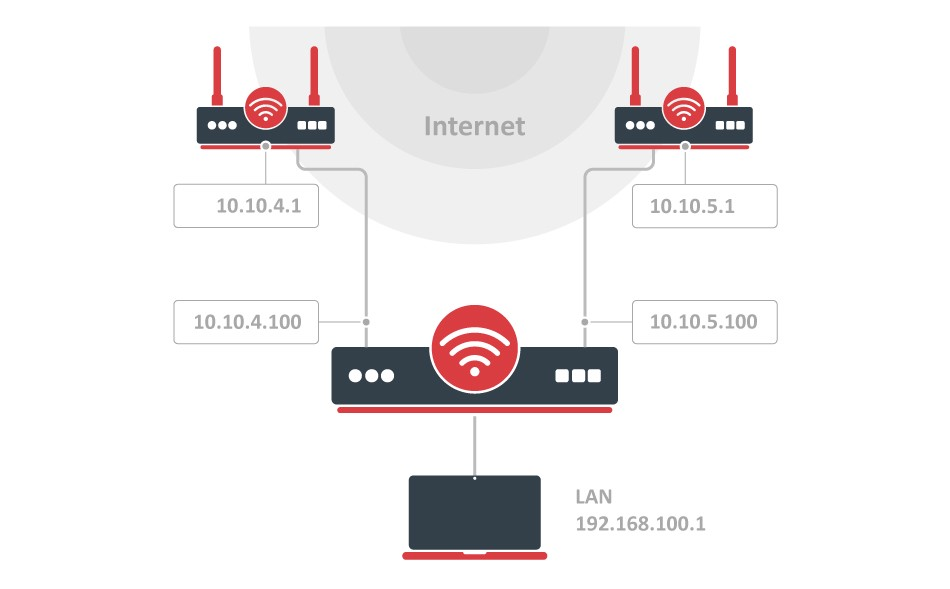
IP Addresses
/ip address add address=10.10.4.100/24 interface=ether_ISP1 network=10.10.4.0
add address=10.10.5.100/24 interface=ether_ISP2 network=10.10.5.0
add address=192.168.100.1/24 interface=ether_LAN network=192.168.100.0
The router has two upstream (ISP) interfaces with the addresses of 10.10.4.100/24 and 10.10.5.100/24. The LAN interface has IP address of 192.168.0.1/24.
We are adding two new Routing tables, which will be used later:
/routing table
add disabled=no fib name=ISP1_table
add disabled=no fib name=ISP2_table
Policy routing
/ip firewall mangle
add action=accept chain=prerouting dst-address=10.10.4.0/24 in-interface=ether_LAN
add action=accept chain=prerouting dst-address=10.10.5.0/24 in-interface=ether_LAN
With policy routing it is possible to force all traffic to the specific gateway, even if traffic is destined to the host (other that gateway) from the connected networks. This way routing loop will be generated and communications with those hosts will be impossible. To avoid this situation we need to allow usage of default routing table for traffic to connected networks.
add action=mark-connection chain=input connection-state=new in-interface=ether_ISP1 new-connection-mark=ISP1
add action=mark-connection chain=input connection-state=new in-interface=ether_ISP2 new-connection-mark=ISP2

add action=mark-connection chain=output connection-mark=no-mark connection-state=new new-connection-mark=ISP1 passthrough=yes per-connection-classifier=both-addresses:2/0
add action=mark-connection chain=output connection-mark=no-mark connection-state=new new-connection-mark=ISP2 per-connection-classifier=both-addresses:2/1
First it is necessary to manage connection initiated from outside - replies must leave via same interface (from same Public IP) request came. We will mark all new incoming connections, to remember what was the interface.
add action=mark-connection chain=prerouting connection-mark=no-mark connection-state=new dst-address-type=!local in-interface=ether_LAN new-connection-mark=ISP1 per-connection-classifier=both-addresses:2/0
add action=mark-connection chain=prerouting connection-mark=no-mark connection-state=new dst-address-type=!local in-interface=ether_LAN new-connection-mark=ISP2 per-connection-classifier=both-addresses:2/1
Action mark-routing can be used only in mangle chain output and prerouting, but mangle chain prerouting is capturing all traffic that is going to the router itself. To avoid this we will use dst-address-type=!local. And with the help of the new PCC we will divide traffic into two groups based on source and destination addressees.
add action=mark-routing chain=output connection-mark=ISP1 new-routing-mark=ISP1_table
add action=mark-routing chain=prerouting connection-mark=ISP1 in-interface=ether_LAN new-routing-mark=ISP1_table

add action=mark-routing chain=output connection-mark=ISP2 new-routing-mark=ISP2_table
add action=mark-routing chain=prerouting connection-mark=ISP2 in-interface=ether_LAN new-routing-mark=ISP2_table
Then we need to mark all packets from those connections with a proper mark. As policy routing is required only for traffic going to the Internet, do not forget to specify in-interface option.
/ip route
add check-gateway=ping disabled=no dst-address=0.0.0.0/0 gateway=10.10.4.1 routing-table=ISP1_table suppress-hw-offload=no
add check-gateway=ping disabled=no dst-address=0.0.0.0/0 gateway=10.10.5.1 routing-table=ISP2_table suppress-hw-offload=no
Create a route for each routing-mark
add distance=1 dst-address=0.0.0.0/0 gateway=10.10.4.1
add distance=2 dst-address=0.0.0.0/0 gateway=10.10.5.1
To enable failover, it is necessary to have routes that will jump in as soon as others will become inactive on gateway failure. (and that will happen only if check-gateway option is active)
NAT
/ip firewall nat
add action=masquerade chain=srcnat out-interface=ether_ISP1
add action=masquerade chain=srcnat out-interface=ether_ISP2
As routing decision is already made we just need rules that will fix src-addresses for all outgoing packets. If this packet will leave via ether_ISP1 it will be NATed to 10.10.4.100, if via ether_ISP2 then NATed to 10.10.5.100
Bonding
Summary
Bonding is a technology that allows aggregation of multiple ethernet-like interfaces into a single virtual link, thus getting higher data rates and providing failover.
Interface bonding does not create an interface with a larger link speed. Interface bonding creates a virtual interface that can load balance traffic over multiple interfaces.
CRS3xx, CRS5xx series switches, CCR2116, CCR2216 routers and 88E6393X, 88E6191X, 88E6190 switch chips support bridge hardware offloading with bonding interfaces. Only 802.3ad and balance-xor bonding modes are hardware offloaded, other bonding modes will use the CPU's resources. The built-in switch chip will always use Layer2+Layer3+Layer4 for a transmit hash policy, changing the transmit hash policy manually will have no effect.
Quick Setup Guide
Let us assume that we have two Ethernet interfaces on each router (Router1 and Router2) and want to get the maximum data rate between these two routers. To make this possible, follow these steps:
- Make sure that you do not have IP addresses on interfaces that will be enslaved for bonding interface.
-
Add bonding interface and IP address on the Router1:
/interface bonding add slaves=ether1,ether2 name=bond1 /ip address add address=172.16.0.1/24 interface=bond1 -
Do the same thing on the Router2:
/interface bonding add slaves=ether1,ether2 name=bond1 /ip address add address=172.16.0.2/24 interface=bond1 -
Test the link from Router1:
[admin@Router1] > ping 172.16.0.2
  SEQ HOST                                 SIZE TTL TIME  STATUS
    0 172.16.0.2                             56  64 0ms
    1 172.16.0.2                             56  64 0ms
    2 172.16.0.2                             56  64 0ms
    sent=3 received=3 packet-loss=0% min-rtt=0ms avg-rtt=0ms max-rtt=0ms
The bonding interface needs a couple of seconds to get connectivity with its peers.
Link monitoring
It is critical that one of the available link monitoring options is enabled. In the above example, if one of the bonded links were to fail, the bonding driver will still continue to send packets over the failed link which will lead to network degradation. Bonding in RouterOS currently supports two schemes for monitoring a link state of slave devices: MII and ARP monitoring. It is not possible to use both methods at the same time due to restrictions in the bonding driver.
ARP Monitoring
ARP monitoring sends ARP queries and uses the response as an indication that the link is operational. The ARP replies are not validated, any received packet by the slave interface will result in the slave interface considered as active. This gives assurance that traffic is actually flowing over the links. If balance-rr and balance-xor modes are set, then the switch should be configured to evenly distribute packets across all links. Otherwise, all replies from the ARP targets will be received on the same link which could cause other links to fail. ARP monitoring is enabled by setting three properties - link-monitoring, arp-ip-targets and arp-interval. The meaning of each option is described later in this article. It is possible to specify multiple ARP targets that can be useful in High Availability setups. If only one target is set, the target itself may go down. Having additional targets increases the reliability of the ARP monitoring.
To enable ARP monitoring on Router1:
/interface bonding set [find name=bond1] link-monitoring=arp arp-ip-targets=172.16.0.2and Router2:
/interface bonding set [find name=bond1] link-monitoring=arp arp-ip-targets=172.16.0.1We will not change the arp-interval value in our example, RouterOS sets arp-interval to 100ms by default. Unplug one of the cables to test if the link monitoring works correctly, you might notice some ping timeouts until arp monitoring detects link failure.
[admin@MikroTik] > ping 172.16.0.2
  SEQ HOST                                     SIZE TTL TIME  STATUS
    0 172.16.0.2                                 56  64 0ms
    1 172.16.0.2                                 56  64 0ms
    2 172.16.0.2                                 56  64 0ms
    3 172.16.0.2                                 56  64 0ms
    4 172.16.0.2                                              timeout
    5 172.16.0.2                                 56  64 0ms
    6 172.16.0.2                                 56  64 0ms
    sent=7 received=6 packet-loss=14% min-rtt=0ms avg-rtt=0ms max-rtt=0ms
For ARP monitoring to work properly it is not required to have any IP address on the device, ARP monitoring will work regardless of the IP address that is set on any interface.
When ARP monitoring is used, bonding slaves will send out ARP requests without a VLAN tag, even if an IP address is set on a VLAN interface in the same subnet as the arp-ip-targets
MII monitoring
MII monitoring monitors only the state of the local interface. MII Type 1 - a device driver determines whether a link is up or down. If the device driver does not support this option then the link will appear as always up. The main disadvantage is that MII monitoring can't tell if the link can actually pass packets or not, even if the link is detected as being up. MII monitoring is configured by setting the variables - link-monitoring and mii-interval.
To enable MII Type1 monitoring on Router1 and Router2:
/interface bonding set [find name=bond1] link-monitoring=miiWe will leave mii-interval to its default value (100ms). When unplugging one of the cables, the failure will be detected almost instantly compared to ARP link monitoring.
Bonding modes
802.3ad
802.3ad mode is an IEEE standard also called LACP (Link Aggregation Control Protocol). It includes automatic configuration of the aggregates, so minimal configuration of the switch is needed. This standard also mandates that frames will be delivered in order and connections should not see misordering of packets. The standard also mandates that all devices in the aggregate must operate at the same speed and duplex mode.
LACP balances outgoing traffic across the active ports based on hashed protocol header information and accepts incoming traffic from any active port. The hash includes the Ethernet source and destination address and if available, the VLAN tag, and the IPv4/IPv6 source and destination address. How this is calculated depends on transmit-hash-policy parameter. The ARP link monitoring is not recommended, because the ARP replies might arrive only on one slave port due to transmit hash policy on the LACP peer device. This can result in unbalanced transmitted traffic, so MII link monitoring is the recommended option.
The layer-3-and-4 transmit hash mode is not fully compatible with LACP. More details can be found in https://www.kernel.org/doc/Documentation/networking/bonding.txt
balance-xor
This mode balances outgoing traffic across the active ports based on the hashed protocol header information and accepts incoming traffic from any active port. The mode is very similar to LACP except that it is not standardized and works with layer-3-and-4 hash policy. The mode can work together with static Link Aggregation Group (LAG) interfaces.
balance-rr
If this mode is set, packets are transmitted in sequential order from the first available slave to the last. The balance-rr is the only mode that will send packets across multiple interfaces that belong to the same TCP/IP connection. When utilizing multiple sending and multiple receiving links, packets are often received out of order, which results in segment retransmission, for other protocols such as UDP it is not a problem if a client software can tolerate out-of-order packets. If a switch is used to aggregate links together, then appropriate switch port configuration is required, however many switches do not support balance-rr. Quick setup guide demonstrates the usage of the balance-rr bonding mode. As you can see, it is quite simple to set up. Balance-rr is also useful for bonding several wireless links, however, it requires equal bandwidth for all bonded links. If the bandwidth of one bonded link drops, then the total bandwidth of bond will be equal to the bandwidth of the slowest bonded link.
active-backup
This mode uses only one active slave to transmit packets. The additional slave only becomes active if the primary slave fails. The MAC address of the bonding interface is presented onto the active port to avoid confusing the switch. Active-backup is the best choice in high availability setups with multiple switches that are interconnected.
The ARP monitoring in this mode will not work correctly if both routers are directly connected. In such setups, MII monitoring must be used or a switch should be put between routers.
broadcast
When ports are configured with broadcast mode, all slave ports transmit the same packets to the destination to provide fault tolerance. This mode does not provide load balancing.
balance-tlb
This mode balances outgoing traffic by peer. Each link can be a different speed and duplex mode and no specific switch configuration is required as for the other modes. The downside of this mode is that only MII link monitoring is supported (ARP link monitoring is ignored when configured) and incoming traffic is not balanced. Incoming traffic will use the link that is configured as "primary".
Configuration example
Let's assume that the router has two links - ether1 max bandwidth is 10Mbps and ether2 max bandwidth is 5Mbps. The first link has more bandwidth so we set it as a primary link:
/interface bonding add mode=balance-tlb slaves=ether1,ether2 primary=ether1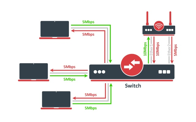
No additional configuration is required for the switch. The image above illustrates how balance-tlb mode works. As you can see router can communicate to all the clients connected to the switch with a total bandwidth of both links (15Mbps). But as you already know, balance-tlb is not balancing incoming traffic. In our example, clients can communicate to the router with a total bandwidth of primary link which is 10Mbps in our configuration.
balance-alb
The mode is basically the same as balance-tlb but incoming IPv4 traffic is also balanced. The receive load balancing is achieved by ARP negotiation. The bonding driver intercepts locally generated ARP messages on their way out and overwrites the source hardware address with the unique address of one of the slaves in the bond such that different peers use different hardware addresses. Only MII link monitoring is supported (ARP link monitoring is ignored when configured), the additional downside of this mode is that it requires device driver capability to change MAC address. The mode is not compatible with local-proxy-arp setting.
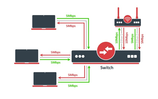
The image above illustrates how balance-alb mode works. Compared to balance-tlb mode, traffic from clients can also use the secondary link to communicate with the router.
Bonding monitoring
Since RouterOS 6.48 version, it is possible to monitor the bonding interface and bonding ports. For the 802.3ad bonding mode, more detailed monitoring options are available.
/interface bonding monitor [find]
                      mode: 802.3ad           active-backup
              active-ports: ether4            ether6
                            ether5
            inactive-ports:                   ether7
            lacp-system-id: CC:2D:E0:11:22:33
      lacp-system-priority: 65535
lacp-partner-system-id: B8:69:F4:44:55:66| mode (802.3ad | active-backup | balance-alb | balance-rr | balance-tlb | balance-xor | broadcast) | Used bonding mode |
| active-ports (interface) | Shows the active bonding ports |
| inactive-ports (interface) | Shows the inactive bonding ports (e.g. a disabled or backup interface) |
| lacp-system-id (MAC address) | Shows the local LACP system ID |
| lacp-system-priority (integer) | Shows the local LACP priority |
| lacp-partner-system-id (MAC address) | Shows the partner LACP system ID |
To monitor individual bonding ports, use a monitor-slaves command.
/interface bonding monitor-slaves bond1
Flags: A - active, P - partner
 AP port=ether4 key=17 flags="A-GSCD--" partner-sys-id=D4:CA:6D:12:06:65 partner-sys-priority=65535 partner-key=9 partner-flags="A-GSCD--"

AP port=ether5 key=17 flags="A-GSCD--" partner-sys-id=D4:CA:6D:12:06:65 partner-sys-priority=65535 partner-key=9 partner-flags="A-GSCD--" | port (interface) | Used bonding port |
| key (integer) | Shows the local LACP aggregation key. The lower 6 bits are automatically assigned based on individual port link speed and duplex. The upper 10 bits can be manually specified using the lacp-user-key setting (available only since RouterOS v7.3). |
| flags (string) |
Shows the local LACP flags: A - activity (link is active, otherwise passive) |
| partner-sys-id (MAC address) | Shows the partner LACP system ID |
| partner-sys-priority (integer) | Shows the partner LACP priority |
| partner-key (integer) | Shows the partner LACP aggregation key |
| partner-flags (string) | Shows the partner LACP flags |
Property Description
This section describes the available bonding settings.
| arp (disabled | enabled | proxy-arp | reply-only; Default: enabled) | Address Resolution Protocol for the interface.
|
| arp-interval (time; Default: 00:00:00.100) | Time in milliseconds defines how often to monitor ARP requests |
| arp-ip-targets (IP address; Default: ) | IP target address which will be monitored if link-monitoring is set to arp. You can specify multiple IP addresses, separated by a comma |
| comment (string; Default: ) | Short description of the interface |
| disabled (yes | no; Default: no) | Changes whether the bonding interface is disabled |
| down-delay (time; Default: 00:00:00) | If a link failure has been detected, the bonding interface is disabled for a down-delay time. The value should be a multiple of mii-interval, otherwise, it will be rounded down to the nearest value. This property only has an effect when link-monitoring is set to mii. |
| forced-mac-address (MAC address; Default: none) | By default, the bonding interface will use the MAC address of the first selected slave interface. This property allows to configure static MAC address for the bond interface (all zeros, broadcast or multicast addresses will not apply). RouterOS will automatically change the MAC address for slave interfaces and it will be visible in /interface ethernet configuration export |
| lacp-rate (1sec | 30secs; Default: 30secs) | Link Aggregation Control Protocol rate specifies how often to exchange with LACPDUs between bonding peers. Used to determine whether a link is up or other changes have occurred in the network. LACP tries to adapt to these changes providing failover. |
| lacp-user-key (integer: 0..1023; Default: 0) | Specifies the upper 10 bits of the port key. The lower 6 bits are automatically assigned based on individual port link speed and duplex. The setting is available only since RouterOS v7.3. |
| link-monitoring (arp | mii | none; Default: mii) | Method to use for monitoring the link (whether it is up or down)
|
| min-links (integer: 0..4294967295; Default: 0) | How many active slave links needed for bonding to become active |
| mii-interval (time; Default: 00:00:00.100) | How often to monitor the link for failures (the parameter used only if link-monitoring is mii) |
| mlag-id (integer: 0..4294967295; Default:) | Changes MLAG ID for bonding interface. The same MLAG ID should be used on both peer devices to successfully create a single MLAG. See more details on MLAG. |
| mode (802.3ad | active-backup | balance-alb | balance-rr | balance-tlb | balance-xor | broadcast; Default: balance-rr) | Specifies one of the bonding policies
|
| mtu (integer; Default: 1500) | Maximum Transmit Unit in bytes. Must be smaller or equal to the smallest L2MTU value of a bonding slave. L2MTU of a bonding interface is determined by the lowest L2MTU value among its slave interfaces |
| name (string; Default: ) | Name of the bonding interface |
| primary (string; Default: none) | Controls the primary interface between active slave ports, works only for active-backup, balance-tlb and balance-alb modes. For active-backup mode, it controls which running interface is supposed to send and receive the traffic. For balance-tlb mode, it controls which running interface is supposed to receive all the traffic, but for balance-alb mode, it controls which interface is supposed to receive the unbalanced traffic (the non-IPv4 traffic). When none of the interfaces are selected as primary, device will automatically select the interface that is configured as the first one. |
| slaves (string; Default: none) | At least two ethernet-like interfaces separated by a comma, which will be used for bonding |
| up-delay (time; Default: 00:00:00) | If a link has been brought up, the bonding interface is disabled for up-delay time and after this time it is enabled. The value should be a multiple of mii-interval, otherwise, it will be rounded down to the nearest value. This property only has an effect when link-monitoring is set to mii. |
| transmit-hash-policy (layer-2 | layer-2-and-3 | layer-3-and-4; Default: layer-2) | Selects the transmit hash policy to use for slave selection in balance-xor and 802.3ad modes
|
Bonding Examples
Bonding EoIP tunnels over two wireless links
This is an example of aggregating multiple network interfaces into a single pipe. In particular, it is shown how to aggregate multiple virtual (EoIP) interfaces to get maximum throughput (MT) with emphasis on availability.
Network Diagram
Two routers R1 and R2 are interconnected via wireless links. Wireless interfaces on both sides have assigned IP addresses.
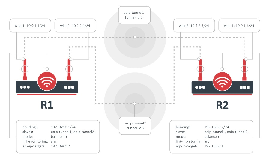
Configuration
Bonding could be used only on OSI layer 2 (Ethernet level) connections. Thus we need to create EoIP interfaces on each of the wireless links. This is done as follows:
on router R1:
/interface eoip add remote-address=10.0.1.1/24 tunnel-id=1
/interface eoip add remote-address=10.2.2.1/24 tunnel-id=2
and on router R2:
/interface eoip add remote-address=10.0.1.2/24 tunnel-id=1
/interface eoip add remote-address=10.2.2.2/24 tunnel-id=2
The second step is to add a bonding interface and specify EoIP interfaces as slaves:
R1:
/interface bonding add slaves=eoip-tunnel1,eoip-tunnel2 mode=balance-rrR2:
/interface bonding add slaves=eoip-tunnel1,eoip-tunnel2 mode=balance-rrThe last step is to add IP addresses to the bonding interfaces:
R1:
/ip address add address 192.168.0.1/24 interface=bonding1R2:
/ip address add address 192.168.0.2/24 interface=bonding1Test the configuration
Now two routers are able to reach each other using addresses from the 192.168.0.0/24 network. To verify bonding interface functionality, do the following:
R1:
/interface monitor-traffic eoip-tunnel1,eoip-tunnel2R2:
/tool bandwidth-test 192.168.0.1 direction=transmitYou should see that traffic is distributed equally across both EoIP interfaces:
/int monitor-traffic eoip-tunnel1,eoip-tunnel2
    received-packets-per-second: 685      685
       received-bits-per-second: 8.0Mbps  8.0Mbps
        sent-packets-per-second: 21       20
           sent-bits-per-second: 11.9kbps 11.0kbps
    received-packets-per-second: 898      899
       received-bits-per-second: 10.6Mbps 10.6Mbps
        sent-packets-per-second: 20       21
           sent-bits-per-second: 11.0kbps 11.9kbps
    received-packets-per-second: 975      975
       received-bits-per-second: 11.5Mbps 11.5Mbps
        sent-packets-per-second: 22       22
           sent-bits-per-second: 12.4kbps 12.3kbps
    received-packets-per-second: 980      980
       received-bits-per-second: 11.6Mbps 11.6Mbps
        sent-packets-per-second: 21       21
           sent-bits-per-second: 11.9kbps 11.8kbps
    received-packets-per-second: 977      977
       received-bits-per-second: 11.6Mbps 11.5Mbps
        sent-packets-per-second: 21       21
           sent-bits-per-second: 11.9kbps 11.8kbps
-- [Q quit|D dump|C-z pause]
Link Monitoring
It is easy to notice that with the configuration above as soon as any individual link fails, the bonding interface throughput collapses. That's because no link monitoring is performed, consequently, the bonding driver is unaware of problems with the underlying links. Enabling link monitoring is a must in most bonding configurations. To enable ARP link monitoring, do the following:
R1:
/interface bonding set bonding1 link-monitoring=arp arp-ip-targets=192.168.0.2R2:
/interface bonding set bonding1 link-monitoring=arp arp-ip-targets=192.168.0.1