Routers
Setup Guides for MikroTik Routers
- MikroTik hAP ax³ Setup Guide
- Creating an Option 43 Entry - Ruckus
- Setting Up Port Forwarding for IPSEC IKE Tunnel
- MikroTik Router Setup Guide with Multiple WAN Connections (SD-WAN) and VLAN Configuration
MikroTik hAP ax³ Setup Guide
This guide will walk you through setting up a MikroTik hAP ax³ router with the following features:
- Two SSIDs: Home and Guest
- Three VLANs: Home, Guest, and IoT
- PPSK (Private Pre-Shared Key): Different keys for Home and IoT networks
- Firewall Rules: Optimized for streaming and gaming
Prerequisites
- MikroTik hAP ax³: Ensure your router is powered on and connected to your network.
- Winbox or Web Interface: Use Winbox or a web browser to access the router's management interface.
- Basic Network Setup: Have an existing internet connection.
Step-by-Step Setup
Step 1: Access MikroTik Router
- Open Winbox: Connect to your MikroTik router using Winbox or the web interface at
http://192.168.88.1. - Log in: Use the default username
adminand no password (change this immediately after login for security).
Step 2: Update RouterOS
Step 3: Create VLANs
Home VLAN
- Name: Home
- VLAN ID: 10
- Interface: Select the interface connected to your network.
Guest VLAN
- Name: Guest
- VLAN ID: 20
- Interface: Select the interface connected to your network.
IoT VLAN
- Name: IoT
- VLAN ID: 30
- Interface: Select the interface connected to your network.
Step 4: Configure Bridge and VLAN Filtering
Bridge Settings
- Name: bridge1
- Add VLANs to the Bridge:
- Go to Bridge > VLANs.
- Add each VLAN to the bridge with the respective VLAN ID and ports.
Step 5: Set Up Wireless Networks (SSIDs)
Home SSID
- Name: Home
- SSID: Home
- Security Profile: Create a new profile with WPA2-PSK.
- VLAN ID: 10
Guest SSID
- Name: Guest
- SSID: Guest
- Security Profile: Create a new profile with WPA2-PSK.
- VLAN ID: 20
- Configure PPSK for Home Network:
- Navigate to Wireless > Security Profiles.
- Create separate security profiles for each key associated with VLAN 10 and VLAN 30.
Step 6: Configure DHCP Servers
Home VLAN DHCP
- Interface: VLAN10
- Address Pool: Create an address pool for VLAN 10.
Guest VLAN DHCP
- Interface: VLAN20
- Address Pool: Create an address pool for VLAN 20.
IoT VLAN DHCP
- Interface: VLAN30
- Address Pool: Create an address pool for VLAN 30.
Step 7: Configure Firewall Rules
Allow Streaming Services
- Chain: forward
- Action: accept
- Src. Address List: Create an address list for streaming services.
Allow Gaming Services
- Chain: forward
- Action: accept
- Src. Address List: Create an address list for gaming services.
Deny Other Traffic
- Chain: forward
- Action: drop
- Log: enabled (for troubleshooting purposes).
- Prioritize Traffic:
- Use Mangle rules to mark packets from specific devices and apply Queue Trees to prioritize gaming and streaming traffic.
Step 8: Test the Configuration
- Connect devices to the Home and Guest SSIDs.
- Test connectivity to ensure devices are assigned to the correct VLANs.
- Verify streaming and gaming performance to ensure traffic is prioritized correctly.
Additional Tips
- Secure Access: Change the default admin password and secure management access.
- Regular Backups: Save your configuration regularly to avoid data loss.
- Firmware Updates: Keep your RouterOS and firmware up-to-date for security and performance.
https://mikrotik.com/product/hap_ax3
Creating an Option 43 Entry - Ruckus
Introduction
This option is used by clients and servers to exchange vendor-specific information. Servers that are not equipped to interpret the information ignore it. Clients that expect but don't receive the information attempt to operate without it.
Option 43 can be especially helpful for pointing Ruckus access points to controller (ZoneDirector or SCG/SZ). The resolution to configure Option 43 is explained below.
Method - Obtaining your Value
You will need to know the following prefix both ZoneDirector(s) and SmartCell Gateway/SmartZone(s).
- Zone Director: 0x30c
- SCG/SZ: 0x60c or 0x60f
You will also need to convert the ASCII text of your controller IP address to HEX. I use the following site for converting but feel free to use whichever you like.
An example of the HEX converter:
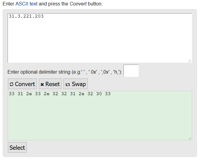
Putting these together will give you your 'value'. For example:
To point a Ruckus AP to a SCG/SZ to example IP 31.3.221.203 would be: 0x60c + 33312e332e3232312e323033 = 0x60c33312e332e3232312e32303
To point a Ruckus AP to a ZD to IP 192.168.1.1 would be: 0x30c + 3139322e3136382e312e31 = 0x30c3139322e3136382e312e31
Method - Setting this in the MikroTik
For the purpose of this article I will assume you have a minimal/basic understanding of the device and know how to login to the MikroTik device.
Open your MikroTik router in Winbox or Webfig. Browse to: IP > DHCP Server > Options > Click the blue '+' to create a new profile
Provide the following:
- Name: Defined by yourself
- Code: This MUST be 43
- Value: Defined by your obtained value
Click 'Apply' and then 'OK'.
This then needs to be applied too your network address. To do this go to: IP > DHCP Server > Networks > Double click the network required (the ones which your AP's will be on) > On DHCP Options click the dropdown and select the profile.
Any AP's now connected to this network should be pointed towards the controller, and appear in their Staging Zone or on the ZD pending any auto provision rules setup on the controller.
Setting Up Port Forwarding for IPSEC IKE Tunnel
Introduction
- Port forwarding, also known as tunnelling, is a network technology procedure that enables external devices to access services on a private network. This is achieved by rerouting communication requests from one address and port number combination to another while packets traverse a network gateway.
- It is extensively used in scenarios where certain applications or services need to be accessible from the internet, including online gaming, torrent downloads, and hosting web servers. These applications typically require direct communication with devices on your private network, which isn’t possible due to NAT (Network Address Translation) mechanisms used by most routers.
- While port forwarding can grant outside access and improve connectivity, it also presents a potential risk as it exposes your internal network to the internet. As such, it’s crucial to exercise due caution by only forwarding necessary ports and implementing robust security measures such as using strong, complex passwords and up-to-date firewall settings.
Method
Step 1: Access MikroTik Router
- Open Winbox or your web browser and connect to your MikroTik router.
- Log in using your credentials.
Step 2: Configure Port Forwarding
- Go to IP > Firewall > NAT.
- Click on the + to add a new rule.
1. Port Forwarding for UDP Port 500 (IKE)
- General Tab:
- Chain: dstnat
- Protocol: udp
- Dst. Port: 500 (this may change, request from the client what is needed. Also ensure that it does not interfere with any existing ports configured)
- Action Tab:
- Action: dst-nat
- To Addresses: Internal IP address (e.g., 192.168.1.2)
- To Ports: 500 (this may change, request from the client what is needed. Also ensure that it does not interfere with any existing ports configured)
2. Port Forwarding for UDP Port 4500 (NAT-T)
- General Tab:
- Chain: dstnat
- Protocol: udp
- Dst. Port: 4500 (this may change, request from the client what is needed. Also ensure that it does not interfere with any existing ports configured)
- Action Tab:
- Action: dst-nat
- To Addresses: Internal IP address (e.g., 192.168.1.2)
- To Ports: 4500 (this may change, request from the client what is needed. Also ensure that it does not interfere with any existing ports configured)
Step 3: Configure Firewall Rules
- Go to IP > Firewall > Filter Rules.
- Click on the + to add new rules.
1. Allow UDP Port 500 (IKE)
- General Tab:
- Chain: forward
- Protocol: udp
- Dst. Port: 500 (this may change, request from the client what is needed. Also ensure that it does not interfere with any existing ports configured)
- Action Tab:
- Action: accept
2. Allow UDP Port 4500 (NAT-T)
- General Tab:
- Chain: forward
- Protocol: udp
- Dst. Port: 4500 (this may change, request from the client what is needed. Also ensure that it does not interfere with any existing ports configured)
- Action Tab:
- Action: accept
Step 4: Sort the Filter Rules
- Drag and drop the filter rules you have created in Step 3 so that they are above any existing 'drop rules'.
Step 5: Ensure IP Forwarding is Enabled
- Go to IP > Settings.
- Make sure IP Forwarding is enabled.
Step 6: Verify Configuration
- Check the NAT Rules:
- Ensure the NAT rules are correctly set up and active.
- Go to IP > Firewall > NAT and verify that the new rules are listed and active.
- Check the Firewall Rules:
- Ensure the firewall rules are correctly set up and active.
- Go to IP > Firewall > Filter Rules and verify that the new rules are listed and active.
- Test the VPN Connection:
- Attempt to establish the VPN connection from the internal router to Azure.
- Verify the connection by checking the VPN status on the internal router.
MikroTik Router Setup Guide with Multiple WAN Connections (SD-WAN) and VLAN Configuration
This guide will help you configure your MikroTik router with the following features:
- Introduction to Multiple WAN Connections (SD-WAN)
- Three WAN Connections: Fiber (Primary), 5G, and Starlink
- Load Balancing and Failover: Prioritize Fiber connection
- Three VLANs: Home, Guest, and IoT
- Firewall Rules: Optimized for streaming and gaming
- Traffic Prioritization: Using Quality of Service (QoS)
Prerequisites
- MikroTik Router: Ensure your device supports the necessary features (e.g., RB4011, CCR series).
- Access to Router Management Interface: Use Winbox or WebFig to configure the router.
- WAN Connections: Have your Fiber, 5G, and Starlink connections physically connected to the router.
- Basic Network Knowledge: Familiarity with network configurations and terms.
Step-by-Step Setup
Step 1: Access the MikroTik Router
- Connect to the Router: Use an Ethernet cable to connect your computer to the router.
- Open Winbox: Download from the MikroTik website if you haven't already.
- Login:
- MAC Address: Use the MAC address to connect if the IP is not set.
- Default Username:
admin - Default Password: (Leave blank initially; change immediately for security)
Step 2: Configure WAN Interfaces
Identify the interfaces connected to your WAN connections.
Assign Names to WAN Interfaces
- Fiber Connection (Primary)
- Interface: e.g.,
ether1 - Name:
WAN_Fiber
- Interface: e.g.,
- 5G Connection
- Interface: e.g.,
ether2 - Name:
WAN_5G
- Interface: e.g.,
- Starlink Connection
- Interface: e.g.,
ether3 - Name:
WAN_Starlink
- Interface: e.g.,
Configure IP Addresses for WAN Interfaces
- Go to:
IP > DHCP Client - Add DHCP Client for each WAN interface:
- Interface:
WAN_Fiber - Use Peer DNS: Yes
- Add Default Route: No (We'll set routes manually)
- Repeat for
WAN_5GandWAN_Starlink
- Interface:
Step 3: Configure Load Balancing and Failover
We'll set up routing rules to prioritize the Fiber connection and use the 5G and Starlink as backups.
Set Default Routes with Different Distances
- Go to:
IP > Routes - Add Route for Fiber Connection
- Destination Address:
0.0.0.0/0 - Gateway: Select the gateway provided by the DHCP client on
WAN_Fiber(e.g.,WAN_Fiberinterface) - Distance:
1(Primary connection)
- Destination Address:
- Add Route for 5G Connection
- Destination Address:
0.0.0.0/0 - Gateway: Select the gateway from
WAN_5G - Distance:
2
- Destination Address:
- Add Route for Starlink Connection
- Destination Address:
0.0.0.0/0 - Gateway: Select the gateway from
WAN_Starlink - Distance:
3
- Destination Address:
Set Up Check Gateway
- Edit Each Route: Enable
Check Gatewaywithpingto monitor the connection.- This allows the router to detect when a connection is down and automatically switch to the next available connection.
Step 4: Configure VLANs
Create VLAN Interfaces
- Go to:
Interfaces - Click:
+(Add New Interface)- Type:
VLAN
- Type:
Home VLAN
- Name:
VLAN_Home - VLAN ID:
10 - Interface: Physical interface connected to your switch (e.g.,
ether5)
Guest VLAN
- Name:
VLAN_Guest - VLAN ID:
20 - Interface:
ether5
IoT VLAN
- Name:
VLAN_IoT - VLAN ID:
30 - Interface:
ether5
Configure Bridge Interface
If using multiple VLANs on a single physical interface, it's good practice to use a bridge.
- Go to:
Bridge - Add New Bridge
- Name:
BR_LAN
- Name:
- Add Ports to Bridge
- Go to:
Bridge > Ports - Add:
ether5toBR_LAN - Add:
VLAN_Home,VLAN_Guest,VLAN_IoTtoBR_LAN
- Go to:
Assign IP Addresses to VLAN Interfaces
- Go to:
IP > Addresses - Add New Address
Home VLAN
- Address:
192.168.10.1/24 - Interface:
VLAN_Home
Guest VLAN
- Address:
192.168.20.1/24 - Interface:
VLAN_Guest
IoT VLAN
- Address:
192.168.30.1/24 - Interface:
VLAN_IoT
Step 5: Configure DHCP Servers for Each VLAN
- Go to:
IP > DHCP Server - Click:
DHCP Setup
Home VLAN DHCP
- Interface:
VLAN_Home - Follow the prompts to set:
- Address Pool:
192.168.10.2-192.168.10.254 - Gateway:
192.168.10.1 - DNS Servers: Use your preferred DNS (e.g.,
8.8.8.8)
- Address Pool:
Guest VLAN DHCP
- Interface:
VLAN_Guest - Address Pool:
192.168.20.2-192.168.20.254 - Gateway:
192.168.20.1 - DNS Servers:
8.8.8.8
IoT VLAN DHCP
- Interface:
VLAN_IoT - Address Pool:
192.168.30.2-192.168.30.254 - Gateway:
192.168.30.1 - DNS Servers:
8.8.8.8
Step 6: Configure Firewall Rules
MikroTik uses a default firewall configuration; we'll modify it to suit our needs.
Enable NAT for Internet Access
- Go to:
IP > Firewall > NAT - Add New NAT Rule
- Chain:
srcnat - Out Interface List:
WAN(We'll create an interface list for WAN interfaces) - Action:
masquerade
- Chain:
Create Interface List for WAN
- Go to:
Interfaces > Interface List - Add New List
- Name:
WAN - Add Interfaces:
WAN_Fiber,WAN_5G,WAN_Starlink
- Name:
Allow Traffic from VLANs to WAN
- Go to:
IP > Firewall > Filter Rules - Add New Rule
- Chain:
forward - Src. Address:
192.168.10.0/24,192.168.20.0/24,192.168.30.0/24 - Out Interface List:
WAN - Action:
accept
- Chain:
Drop Inter-VLAN Traffic
- Add New Rule
- Chain:
forward - Src. Address List: Create an address list for your VLAN subnets.
- Name:
VLAN_Networks - Addresses:
192.168.10.0/24,192.168.20.0/24,192.168.30.0/24
- Name:
- Dst. Address List:
VLAN_Networks - Action:
drop - Place this rule before the rule that accepts established/related traffic.
- Chain:
Allow Established and Related Traffic
- Ensure you have a rule to accept established and related connections
- Chain:
forward - Connection State:
established, related - Action:
accept
- Chain:
Drop Invalid Traffic
- Add Rule
- Chain:
forward - Connection State:
invalid - Action:
drop
- Chain:
Step 7: Configure Traffic Prioritization (QoS)
We'll use Simple Queues to prioritize gaming and streaming traffic.
Identify Gaming and Streaming Traffic
-
Go to:
IP > Firewall > Mangle -
Add New Rule for Gaming Traffic
- Chain:
forward - Protocol: Select protocols used by games (e.g., TCP/UDP ports)
- Dst. Port: Add known gaming ports
- Action:
mark-packet - New Packet Mark:
Gaming_Traffic - Passthrough:
yes
- Chain:
-
Add New Rule for Streaming Traffic
- Chain:
forward - Dst. Address List: Create an address list for streaming services (e.g., Netflix IP ranges)
- Action:
mark-packet - New Packet Mark:
Streaming_Traffic - Passthrough:
yes
- Chain:
Create Simple Queues
- Go to:
Queues > Simple Queues
Gaming Traffic Queue
- Name:
Priority_Gaming - Target:
192.168.10.0/24(Assuming gaming devices are on the Home VLAN) - Max Limit: Set according to your bandwidth
- Limit At: Set minimum guaranteed bandwidth
- Priority:
1(Highest priority) - Advanced Tab:
- Packet Marks:
Gaming_Traffic
- Packet Marks:
Streaming Traffic Queue
- Name:
Priority_Streaming - Target:
192.168.10.0/24 - Max Limit: Set according to your bandwidth
- Limit At: Set minimum guaranteed bandwidth
- Priority:
2 - Advanced Tab:
- Packet Marks:
Streaming_Traffic
- Packet Marks:
Step 8: Secure the Router
Change the Default Admin Password
- Go to:
System > Users - Edit:
admin - Set a strong password
Disable Unnecessary Services
- Go to:
IP > Services - Disable services you don't use (e.g., FTP, Telnet)
- Ensure Winbox and SSH are secured
Enable HTTPS for WebFig
- Go to:
IP > Services - Enable:
www-ssl - Disable:
www(HTTP)
Step 9: Test the Configuration
- VLAN Connectivity: Connect devices to each VLAN and ensure they receive the correct IP addresses.
- Internet Access: Verify that devices can access the internet.
- Failover: Disconnect the Fiber connection to test if traffic fails over to 5G or Starlink.
- Load Balancing: Monitor traffic using
Tools > Torchto see if load balancing works as expected. - QoS Effectiveness: Use bandwidth-intensive applications to test if gaming and streaming traffic are prioritized.
Additional Tips
- Regular Backups: Go to
Files, select your configuration file, and download it to your computer. - Firmware Updates: Check
System > Packagesfor updates and upgrade to the latest stable version. - Monitor Traffic: Use
Tools > GraphingorQueues > Queue Treeto monitor bandwidth usage. - Logs: Check
Logfor any errors or unusual activity.
By following this guide, you should have a MikroTik router configured with multiple WAN connections, VLAN segmentation, firewall rules, and QoS prioritization. The Fiber connection is set as the primary WAN, with 5G and Starlink serving as backup connections to ensure uninterrupted internet access.
Note: MikroTik routers are highly versatile but can be complex. Always make sure to back up your configuration before making significant changes, and consult the MikroTik Wiki or Forums if you encounter issues.